The gas industry periodically updates technical standards to reflect evolving safety requirements, industry experience and improvements in best practice. One of the most significant recent updates affecting gas engineers is the publication of IGEM/UP/1B Edition 4, which introduces important changes to the way tightness testing and direct purging are carried out on domestic and small commercial gas installations.
Published in March 2026, IGEM/UP/1B Edition 4 replaces Edition 3. However, both standards remain valid during a six-month transition period to allow engineers and Gas Safe registered businesses sufficient time to become familiar with the new requirements. From 1 October 2026, all tightness testing must be carried out in accordance with Edition 4.
While the fundamental process of tightness testing remains familiar, several important procedural changes have been introduced. These changes affect pressure interpretation, installation volume calculations, appliance isolation requirements and purging procedures.
For engineers carrying out commissioning, servicing, landlord safety inspections, and fault-finding, understanding these changes is essential for maintaining compliance and ensuring installations remain safe.
IGEM/UP/1B Edition 4
IGEM/UP/1B provides guidance on tightness testing and direct purging for small natural gas, LPG, and LPG air installations.
The standard exists to ensure engineers apply a consistent approach when:
- checking installations for gas escapes
- verifying installation integrity
- carrying out purging procedures
- assessing safety before commissioning appliances
Edition 4 introduces changes designed to improve confidence in testing results and help distinguish between acceptable appliance-related pressure drops and genuine installation pipework leakage.
The result is a more robust testing process that provides greater assurance that installation pipework remains gas-tight.
Transition Arrangements For Engineers
Gas Safe Register has allowed a six-month implementation period to support the transition from Edition 3 to Edition 4.
During this period:
- either Edition 3 or Edition 4 may be used
- businesses should begin updating procedures and documentation
- engineers should familiarise themselves with installation volume calculations and revised testing procedures
From 1 October 2026:
- Edition 3 is withdrawn
- Edition 4 becomes mandatory
- all tightness testing must follow the new requirements
For businesses with multiple engineers, now is the ideal time to update internal procedures and provide refresher training.
Existing Elements That Remain Unchanged
Despite the updates, many familiar elements of the procedure remain the same.
These include:
- visual inspection of the installation
- Emergency Control Valve let-by testing
- stabilisation periods
- test durations
- use of approved pressure testing equipment
- general testing principles
This means engineers do not need to relearn tightness testing completely. Instead, they must understand the additional steps introduced by Edition 4.
Safe To Touch Testing Requirements
One of the first procedural additions is the introduction of a safe to touch test using a suitable no-contact gas detector.
Following the visual inspection, engineers should perform a sweeping scan of all exposed metallic pipework.
The purpose of this check is to:
- identify existing gas escapes before testing begins
- improve engineer safety
- provide an additional layer of protection during inspection
This initial sweep should be methodical and cover all accessible pipework throughout the installation. Any positive indications must be investigated before proceeding further.
Emergency Control Valve Let By Testing
Following the safe to touch test, the engineer carries out the Emergency Control Valve let-by test.
The procedure remains unchanged:
- pressure is established between 7 mbar and 10 mbar
- the valve is observed for one minute
- any pressure increase may indicate valve let-by
Only once the engineer is satisfied that the ECV is functioning correctly should the tightness test proceed.
Updated Tightness Test Pressure Requirements
A significant addition in Edition 4 concerns minimum test pressure requirements.
The standard now states that where the minimum test pressure for the fuel gas cannot be achieved, the installation must be isolated and investigations undertaken before continuing.
For natural gas installations:
- the normal test pressure remains 20 mbar
- testing may proceed at a minimum of 18 mbar if 20 mbar cannot be achieved
- operating pressure checks must then be carried out in accordance with IGEM/G/13 guidance
This change helps ensure that engineers identify supply-related issues rather than unknowingly accepting potentially inaccurate test results.
Stabilisation and Test Duration
Where the required test pressure has been achieved:
- allow one minute stabilisation
- perform a further two minute test period
- monitor the pressure gauge throughout
If there is no perceptible movement of the gauge and no reported gas odour, the installation passes the tightness test.
However, when movement is detected, the assessment process now differs significantly from that in the previous edition.
Installation Volume Calculations
One of the most important changes in Edition 4 is the move away from meter size based permissible limits.
Permissible pressure drops are now determined using installation volume calculations.
This means engineers must understand:
- installation volume principles
- pipework volume calculations
- hidden pipework estimation
- interpretation of permissible limits
Installation volume refers to the total volume of gas contained within the installation or the section being tested.
By calculating installation volume, engineers can determine whether observed pressure movement falls within acceptable limits.
Calculating Installation Volume
Installation volume is calculated using:
- pipe diameter
- pipe length
- total pipework arrangement
Where sections of pipework are concealed, engineers should apply reasonable engineering judgement.
The guidance recommends assuming the largest visible pipe size continues through hidden sections of pipework until proven otherwise. This approach ensures any installation volume calculation errs on the side of safety.
For example, if visible pipework is 28 mm and disappears into a wall before reappearing at a smaller size, engineers should assume the concealed section remains 28 mm throughout.
This prevents installation volume being underestimated and avoids applying larger permissible limits than intended.
Interpreting Pressure Movement
In the previous edition, engineers assessed permissible pressure drops using meter-size criteria.
Edition 4 now requires pressure movement to be assessed using installation volume.
For natural gas installations:
- any drop above 1 mbar requires installation volume assessment
- pressure movement must be compared against the relevant permissible limits table
- no smell of gas must be present for permissible limits to apply
Where pressure movement exceeds permissible limits:
- the escape must be located
- repairs must be completed
- the installation must be retested
- or the installation must be made safe
The new process provides a more accurate assessment of installation condition and improves confidence in testing outcomes.
Appliance Isolation Requirements
One of the most significant operational changes introduced by IGEM/UP/1B Edition 4 is the requirement to isolate appliances where pressure movement has been detected and shown to fall within the permissible limits for the calculated installation volume.
While installation volume calculations have received considerable attention, the appliance isolation requirement represents the most important practical change engineers are likely to encounter during tightness testing.
Purpose Of Appliance Isolation
The primary purpose of appliance isolation is to determine whether pressure movement originates from connected appliances or from the installation pipework itself.
Gas appliances contain a variety of internal components including gas valves, regulators, governors and control assemblies. During a tightness test, these components may contribute to pressure movement that could be mistaken for leakage within the installation.
By isolating appliances and repeating the test on the pipework only, engineers can remove appliance influences from the assessment and gain greater confidence in the integrity of the installation.
This additional verification stage strengthens the overall testing process and reduces uncertainty when interpreting results.
Why Edition 4 Introduced The Change
Industry experience demonstrated that pressure movement falling within permissible limits did not always guarantee that installation pipework was free from defects.
While previous procedures provided a practical framework for assessing installations, they could not always distinguish between pressure movement caused by appliances and pressure movement caused by pipework leakage.
The revised procedure has therefore been introduced to:
- improve confidence in test outcomes
- reduce the likelihood of hidden gas escapes being overlooked
- provide greater consistency across the industry
- strengthen gas safety standards
- support a more evidence based approach to testing
The result is a tighter and more robust verification process.
Appliance Leakage Versus Pipework Leakage
A key principle behind Edition 4 is the need to distinguish between appliance related pressure movement and genuine installation leakage.
Where pressure movement is observed during a tightness test, there may be several possible explanations:
- appliance valve seepage
- regulator influences
- pressure stabilisation effects
- concealed pipework leakage
- minor installation defects
Without further investigation, it can be difficult to determine the source of the movement.
The appliance isolation stage removes appliance-related influences from the equation, allowing engineers to assess the installation pipework independently.
If no perceptible movement remains during the repeat test, confidence in the installation integrity increases significantly.
If movement persists, further investigation is necessary.
Testing Sequence
Where pressure movement has been identified and shown to fall within the permissible limits, the engineer should:
- Complete the initial tightness test.
- Calculate installation volume where required.
- Compare the observed pressure movement against the permissible limits.
- Isolate appliances where practicable.
- Repeat the tightness test on the installation pipework only.
- Confirm there is no perceptible movement during the repeat test.
- Reinstate appliances and complete final checks.
If movement remains after appliance isolation, the installation cannot be considered satisfactory, and further investigation is required.
Situations Where Isolation Is Not Practicable
Not all installations allow straightforward appliance isolation.
Engineers may encounter:
- older installations without suitable isolation arrangements
- restricted access locations
- integrated appliance systems
- specialist commercial equipment
- situations where isolation may create additional risks
In these circumstances, engineers should follow the intent of the standard while applying appropriate professional judgement.
Engineering Judgement Requirements
Engineering judgement remains an important part of the testing process.
When applying the revised procedure, engineers should consider:
- installation design
- accessibility of equipment
- availability of isolation points
- safety implications of proposed actions
- evidence provided by the test results
Where decisions differ from standard scenarios, those decisions should be documented clearly.
Good documentation demonstrates competence and provides evidence of the engineer’s reasoning.
Mistakes Engineers May Make
As engineers become familiar with Edition 4, several common mistakes are likely to emerge.
These include:
- failing to isolate appliances when required
- assuming movement is appliance related without verification
- incorrect installation volume calculations
- overlooking concealed pipework
- failing to complete the pipework only retest
- poor documentation of findings
- reinstating appliances before all checks have been completed
A structured approach to testing and documentation will help avoid these issues.
Engineering Significance Of The New Procedure
While many of the changes introduced by Edition 4 appear procedural, their significance extends far beyond simply adding steps to a tightness test.
The revised methodology represents a move towards a more accurate assessment of installation integrity and a greater understanding of the source of pressure movement.
Why Meter Size Criteria Were Replaced
Previous editions relied upon meter size when determining permissible pressure movement.
While practical, this approach did not always reflect the actual volume of gas contained within the installation.
Two installations supplied by the same meter could contain vastly different pipework volumes and therefore behave differently during testing.
Installation volume calculations provide a more accurate representation of the installation being assessed.
Benefits Of Installation Volume Calculations
The new approach offers several benefits:
- more accurate pressure movement assessment
- better representation of installation characteristics
- improved consistency between installations
- stronger technical justification for decisions
- improved reliability of test outcomes
These benefits support more effective decision-making and improved compliance.
Increased Confidence In Test Outcomes
The combination of installation volume calculations and appliance isolation requirements provides engineers with significantly more information before determining whether an installation is satisfactory.
Rather than relying solely on pressure movement figures, engineers can now investigate the source of movement more effectively.
This leads to greater confidence in pass-or-fail decisions.
Reduction In False Pass Results
One of the primary objectives of the revised procedure is to reduce the likelihood that installations will pass a tightness test when defects remain.
By introducing additional verification stages, Edition 4 reduces the likelihood that concealed leakage will be overlooked.
Improved Leak Identification
Separating appliance influences from pipework performance allows engineers to identify the source of pressure movement more accurately.
This supports more efficient fault finding and improves the overall integrity of the testing process.
Pressure Interpretation Scenarios
The following examples demonstrate how the revised procedure should be applied in real situations.
Scenario One: No Perceptible Movement
An engineer completes a tightness test and observes no perceptible movement throughout the test period.
There is no smell of gas and all preliminary checks are satisfactory.
Engineer Decision:
- installation passes the tightness test
- no installation volume calculation required
- no appliance isolation required
- complete final verification checks
This remains the most straightforward outcome.
Scenario Two: Pressure Movement Within Permissible Limits
Pressure movement is observed during the test period.
Installation volume calculations are completed and confirm that the movement falls within the permissible limits.
Engineer Decision:
- isolate appliances where practicable
- repeat the tightness test on the installation pipework
- verify that no perceptible movement remains
The installation cannot be considered satisfactory until this additional stage has been completed.
Scenario Three: Pressure Movement Exceeds Permissible Limits
Pressure movement is detected, and installation volume calculations show that the movement exceeds the allowable limit.
Engineer Decision:
- fail the tightness test
- investigate the source of the gas escape
- repair defects where possible
- retest the installation following corrective action
Further action may be required depending on the severity of the defect.
Scenario Four: Movement Remains After Appliance Isolation
The engineer isolates appliances and repeats the tightness test.
Pressure movement is present during the pipework-only test.
Engineer Decision:
- installation fails the tightness test
- further investigation is required
- the gas escape must be located
- repairs must be completed before retesting
- the installation may require classification under the Unsafe Situations Procedure
This scenario demonstrates why the appliance isolation stage has become such an important part of the revised methodology.
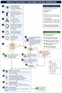
Tightness Testing Reference Table
The following table provides a practical reference for engineers carrying out tightness testing under IGEM/UP/1B Edition 4.
| Test Outcome | Engineer Action | Result |
|---|---|---|
| No perceptible movement | Complete testing procedure | Pass |
| Pressure movement detected | Calculate installation volume | Further assessment required |
| Movement within permissible limits | Isolate appliances and repeat test | Pipework verification required |
| No movement after appliance isolation | Reinstate appliances and complete checks | Pass |
| Movement remains after appliance isolation | Locate and repair escape | Fail |
| Pressure movement exceeds permissible limits | Investigate, repair and retest | Fail |
Leak Detection Fluid Requirements
Although pressure testing remains the primary method of assessing gas soundness, leak detection fluid continues to play an important role within the overall testing process.
Following completion of the tightness test, any disturbed joints should be checked with a suitable leak-detection fluid before the installation is returned to service.
When Leak Detection Fluid Must Be Used
Leak detection fluid should be used whenever:
- a test nipple has been disturbed
- a meter connection has been loosened
- an appliance has been disconnected and reconnected
- an appliance isolation valve has been operated
- pipework joints have been disturbed during testing
- repairs have been completed following a gas escape
This final verification stage provides additional assurance that the joints remain gas-tight.
Disturbed Joints
Every joint disturbed during testing should be considered a potential source of leakage until proven otherwise.
Particular attention should be paid to:
- meter unions
- appliance connections
- test nipples
- isolation valves
- compression fittings
Engineers should visually inspect all tested joints after applying leak-detection fluid and allow sufficient time for any indication of leakage to appear.
Appliance Reconnection
Where appliances have been isolated or disconnected during testing, all reconnections should be verified with leak-detection fluid before the appliance is returned to service.
This requirement applies even where the installation has successfully passed the tightness test.
Test Nipple Verification
Test nipples are among the most commonly disturbed components during gas testing.
Following removal of the manometer:
- the test nipple should be tightened correctly
- leak detection fluid should be applied
- the connection should be observed carefully
Many minor gas escapes occur at poorly reinstated test nipples.
Leak Detection Fluid Mistakes
Common errors include:
- applying insufficient fluid
- failing to cover the entire joint
- wiping the fluid away too quickly
- failing to inspect reinstated test nipples
- relying solely on electronic detectors
- overlooking appliance connections
A systematic approach helps ensure no disturbed connection is missed.
Purging Procedure Changes
Alongside the changes to tightness testing, Edition 4 introduces revised requirements for calculating purge volume.
While the purging process itself remains largely familiar, the way purge volumes are calculated has changed significantly.
Why Purge Volume Calculations Changed
Previous editions allowed engineers to use assumptions for certain smaller installations.
While practical, these assumptions did not always accurately reflect the volume of gas contained within the installation.
Edition 4 aligns purge calculations with installation volume calculations, creating a more consistent and technically accurate approach.
Previous Approach
Historically:
- smaller installations could utilise assumed purge volumes
- calculations were not always required
- purge requirements were often linked to installation type rather than actual volume
This simplified the process but reduced precision.
New Approach
Edition 4 requires engineers to calculate installation volume before determining purge volume.
This ensures purging requirements are based upon the actual characteristics of the installation.
The result is:
- improved consistency
- greater accuracy
- enhanced technical justification
Purge Volume Formula
The revised formula is:
Purge Volume = Installation Volume × 1.5
This calculation should now be applied when determining purge requirements.
Worked Example
Assume an installation volume of:
0.04 m³
Purge volume becomes:
0.04 × 1.5 = 0.06 m³
The engineer would then select the appropriate purge procedure based upon this calculated volume.
Natural Gas Versus LPG
Although the calculation methodology has changed, engineers should remember that purging procedures differ depending upon the fuel involved.
For Natural Gas installations:
- smaller volumes may be purged directly where permitted
- larger volumes require purge to ignition procedures
For LPG installations:
- purge to ignition procedures generally apply
- additional attention must be given to the behaviour of heavier than air gases
For LPG Air systems:
- procedures must follow the specific guidance contained within the standard
Engineers should always consult current guidance before undertaking purging operations.
Documentation Requirements Under Edition 4
Documentation has become increasingly important under the revised standard.
The introduction of installation volume calculations, appliance isolation requirements, and revised pressure interpretation means that engineers must now record more information than in previous editions.
Legal Protection
Accurate records provide evidence that the engineer followed the correct procedure and exercised appropriate professional judgement.
Should questions arise in the future regarding the installation, documentation may become a critical source of evidence.
Audit Evidence
Gas Safe inspections, internal audits and quality assurance reviews increasingly focus on documented evidence.
Engineers should be able to demonstrate:
- installation volume calculations
- pressure readings
- appliance isolation decisions
- retest results
- final conclusions
ACS Implications
As Edition 4 becomes embedded within industry practice, assessors are likely to expect greater emphasis on documentation standards.
Candidates should become familiar with recording:
- calculations
- observations
- procedural decisions
- corrective actions
Customer Records
Clear documentation also benefits customers.
Records provide evidence of:
- work completed
- tests undertaken
- defects identified
- repairs completed
- safety decisions made
Company Procedures
Gas Safe registered businesses should review:
- job sheets
- electronic records
- testing forms
- technical procedures
Many existing documents will need to be updated to meet the new requirements introduced by Edition 4.
Tightness Testing and Unsafe Situations
A failed tightness test should never be viewed simply as a procedural issue. In many cases, pressure movement that exceeds permissible limits or persists after appliance isolation may indicate a gas leak that requires further investigation under the Gas Industry Unsafe Situations Procedure.
The engineer’s responsibility extends beyond identifying a defect. They must also assess the potential danger presented by that defect and take appropriate action to protect occupants and property.
Gas Escapes and Unsafe Situations
Not every gas escape presents the same level of risk.
Factors influencing the severity of the situation include:
- the size of the leak
- the location of the leak
- the likelihood of gas accumulation
- the presence of ignition sources
- ventilation conditions
- accessibility of the affected area
A small leak in a well-ventilated external location may present a significantly different risk profile to a leak within a concealed void or occupied room.
Engineers must therefore assess both the defect itself and the circumstances surrounding it.
At Risk Classifications
An installation may be classified as At Risk where a recognised fault exists that could become dangerous if one further fault or event occurs.
Examples may include:
- minor gas leakage requiring corrective action
- inadequate ventilation combined with appliance defects
- deteriorating pipework showing signs of future failure
- situations where safety margins have been reduced
Where an installation is classified as At Risk, the responsible person should be advised of the situation and appropriate action taken in accordance with current procedures.
Immediately Dangerous Classifications
An Immediately Dangerous situation exists where there is a current danger to life or property.
Examples may include:
- significant gas escapes
- active gas accumulation within a building
- uncontrolled gas release
- severely damaged pipework
- installations presenting an immediate risk of fire or explosion
In these circumstances, immediate action is required to remove the danger.
Isolation Procedures
Where a dangerous condition exists, isolation may be necessary to prevent further risk.
Depending upon the circumstances, this may involve:
- isolating individual appliances
- isolating sections of pipework
- closing the Emergency Control Valve
- disconnecting unsafe equipment
Engineers should always follow current industry procedures and document actions taken.
Customer Communication
Technical competence alone is not sufficient when dealing with unsafe situations.
Engineers must also communicate clearly with customers.
Customers should understand:
- the nature of the defect
- the risks involved
- actions taken to make the installation safe
- any limitations placed upon the installation
- recommendations for corrective work
Clear communication helps avoid misunderstandings and demonstrates professionalism.
Documentation Requirements
Whenever an unsafe situation is identified, records should include:
- the nature of the defect
- classification assigned
- actions taken
- customer discussions
- warnings issued
- any refusal to allow remedial action
Good documentation protects both the engineer and the customer.
Frequently Asked Questions
How Should Hidden Pipework Be Calculated?
Concealed pipework presents one of the most common challenges under Edition 4.
Where pipework cannot be fully inspected, engineers should use reasonable engineering judgement and assume the largest visible pipe diameter continues through the concealed section unless evidence suggests otherwise.
This approach provides a conservative calculation and prevents installation volume from being underestimated.
Do Existing Installations Need To Be Retested Under Edition 4?
No.
Existing installations do not automatically require retesting simply because the standard has changed.
However, any tightness testing carried out after implementation of Edition 4 should follow the revised procedure.
Are Appliance Isolation Procedures Required On Every Tightness Test?
No.
Appliance isolation becomes necessary when pressure movement has been detected and shown to fall within the permissible limits for the calculated installation volume.
Where no perceptible movement is present, appliance isolation is not required.
How Accurate Must Installation Volume Calculations Be?
Installation volume calculations should be sufficiently accurate to allow correct interpretation of pressure movement.
Engineers should use measured dimensions wherever possible and apply reasonable assumptions when dealing with concealed pipework.
What If Pressure Movement Cannot Be Explained?
Where pressure movement remains unexplained after appliance isolation and repeat testing, the installation should not be considered satisfactory.
Further investigation is required until the cause has been identified and appropriate action taken.
Engineer Errors Under Edition 4
As with any major technical update, common mistakes are likely to emerge during the transition period.
Understanding these issues can help engineers avoid unnecessary compliance problems.
Installation Volume Calculation Errors
The most obvious risk involves incorrect installation volume calculations.
Common mistakes include:
- inaccurate pipe measurements
- incorrect pipe diameter assumptions
- failure to include concealed sections
- mathematical errors
- use of incorrect volume data
Even small errors may affect pressure interpretation.
Appliance Isolation Mistakes
Many engineers will be unfamiliar with the new isolation requirements.
Common issues include:
- failing to isolate appliances when required
- incomplete isolation
- failing to perform the pipework only retest
- incorrectly interpreting retest results
These errors could lead to incorrect conclusions regarding installation integrity.
Pressure Interpretation Mistakes
Edition 4 requires engineers to move beyond a simple pass or fail approach.
Common interpretation errors include:
- misunderstanding permissible limits
- incorrect application of installation volume calculations
- failure to recognise when further investigation is required
- overlooking the significance of repeat testing
Poor Documentation
Even where testing is completed correctly, poor documentation can create problems during audits and inspections.
Engineers should ensure all calculations, observations and decisions are recorded clearly.
Incorrect Retesting Procedures
The effectiveness of appliance isolation depends upon proper retesting.
Common errors include:
- shortening test periods
- failing to stabilise pressure correctly
- incomplete appliance isolation
- inadequate recording of results
A consistent and methodical approach helps avoid these issues.
ACS Assessment Implications
The introduction of Edition 4 is likely to have a significant impact on ACS reassessment activities.
Engineers should expect both knowledge-based and practical assessment elements to reflect the revised requirements.
Knowledge Requirements
Candidates should be able to demonstrate understanding of:
- installation volume calculations
- pressure interpretation
- appliance isolation requirements
- purge volume calculations
- documentation standards
- unsafe situations implications
Assessors will increasingly expect engineers to understand not only the procedure but also the reasoning behind it.
Practical Assessment Expectations
Practical assessments may require candidates to:
- carry out installation volume calculations
- interpret pressure movement correctly
- determine appropriate actions
- complete appliance isolation procedures
- document findings accurately
The focus will be on demonstrating competence in real scenarios.
Reassessment Preparation
Engineers approaching ACS reassessment should review:
- IGEM/UP/1B Edition 4
- current Gas Safe guidance
- unsafe situations procedures
- gas soundness testing principles
- installation volume calculation methods
Preparation should focus on understanding as well as memorisation.
Candidate Failures
Areas likely to cause difficulty include:
- incorrect volume calculations
- misunderstanding pressure limits
- failure to apply appliance isolation correctly
- poor documentation
- weak technical justification for decisions
Familiarity with the revised standard will significantly improve assessment performance.
Tightness Testing Compliance Checklist
| Requirement | Complete |
|---|---|
| Visual inspection completed | ☐ |
| Safe to touch test completed | ☐ |
| ECV let by test completed | ☐ |
| Correct test pressure achieved | ☐ |
| Installation volume calculated where required | ☐ |
| Pressure movement assessed | ☐ |
| Appliances isolated where required | ☐ |
| Pipework only retest completed | ☐ |
| Leak detection fluid checks completed | ☐ |
| Purge calculations completed | ☐ |
| Results documented | ☐ |
Business Implications For Gas Safe Registered Companies
The impact of Edition 4 extends beyond individual engineers.
Gas Safe registered businesses must ensure their systems, procedures and documentation reflect the revised requirements.
Updating Paperwork
Existing forms may need revision to include:
- installation volume calculations
- appliance isolation records
- pipework retest results
- purge volume calculations
Without these additions, engineers may struggle to demonstrate compliance.
Updating Procedures
Technical procedures should be reviewed and updated to reflect:
- revised testing methodology
- appliance isolation requirements
- documentation expectations
- new purge calculation methods
Engineer Training
Managers should ensure all engineers understand:
- the reasons behind the changes
- practical implementation requirements
- common compliance risks
Training reduces inconsistency and improves overall quality.
Internal Audits
Technical audits should verify:
- correct calculations
- appropriate decision making
- accurate record keeping
- procedural compliance
Regular auditing helps identify issues before they become wider problems.
Technical Supervision
Supervisors and technical managers play an important role in supporting engineers through the transition period.
Providing guidance, reviewing documentation and reinforcing good practice will help ensure consistent implementation across the business.
Gas Training Courses In Staffordshire
The introduction of IGEM/UP/1B Edition 4 highlights the importance of keeping technical knowledge aligned with current industry standards.
Changes such as installation volume calculations, appliance isolation requirements, and revised purge volume procedures represent a significant shift in how gas soundness testing is carried out. Engineers must not only understand the new process but also the reasoning behind it to apply the requirements confidently on site.
Whether preparing for an ACS reassessment, returning to the industry after a period away from gas work, or simply maintaining professional competence, regular technical gas training helps ensure that procedures are applied correctly and consistently.
At Staffordshire Training Services, gas engineers can develop and maintain competence through ACS assessments, reassessments, and technical training covering gas safety legislation, tightness testing, procedures for unsafe situations, combustion analysis, and gas soundness testing.
As industry standards continue to evolve, ongoing professional development remains one of the most effective ways to maintain compliance, strengthen technical confidence and support safe working practices.
Maintaining Compliance Under Edition 4
IGEM/UP/1B Edition 4 introduces some of the most significant changes to gas soundness testing procedures in recent years.
The move from meter-size criteria to installation-volume calculations provides a more accurate method for assessing pressure movement. At the same time, the introduction of appliance isolation requirements helps engineers distinguish between appliance-related influences and genuine installation leakage.
Although the fundamental principles of tightness testing remain unchanged, the revised procedure requires a more detailed assessment of installation integrity and a greater emphasis on decision making.
Engineers who understand the purpose behind the changes, apply the procedures consistently and maintain accurate records will be well positioned to meet the requirements of the new standard.
Ultimately, Edition 4 is not simply about changing the way tightness tests are carried out. It is about improving confidence in results, strengthening leak identification and supporting the highest standards of gas safety throughout the industry.
Related Articles
- Tightness Testing and Gas Soundness For Engineers
- Combustion Analysis and Flue Gas Testing For Gas Engineers
- Gas Pressure Testing and Appliance Performance For Engineers
- Ventilation and Flueing Requirements For Gas Appliances
- Gas Tightness Testing Fault-Finding Techniques
Prefer an AI Summary?