Buffer vessels are one of the most discussed components in modern heat pump installations. Some manufacturers recommend them in certain applications, while others design systems that operate without one. This has led to considerable debate within the heating industry, particularly as more engineers transition from traditional boiler installations to renewable heating technologies.
Despite these differing approaches, buffer vessels remain an important part of many heat pump systems. When specified and installed correctly, they can improve hydraulic performance, increase system stability and help protect the heat pump from operating conditions that reduce efficiency.
For renewable installers, understanding the purpose of a buffer vessel is essential. It is not simply an additional cylinder fitted alongside the heat pump. It is a hydraulic component that can influence flow rates, system volume, compressor operation and overall system performance.
This examines the role of buffer vessels in heat pump systems, the situations where they are beneficial and the design considerations installers should understand before specifying one.
Buffer Vessels
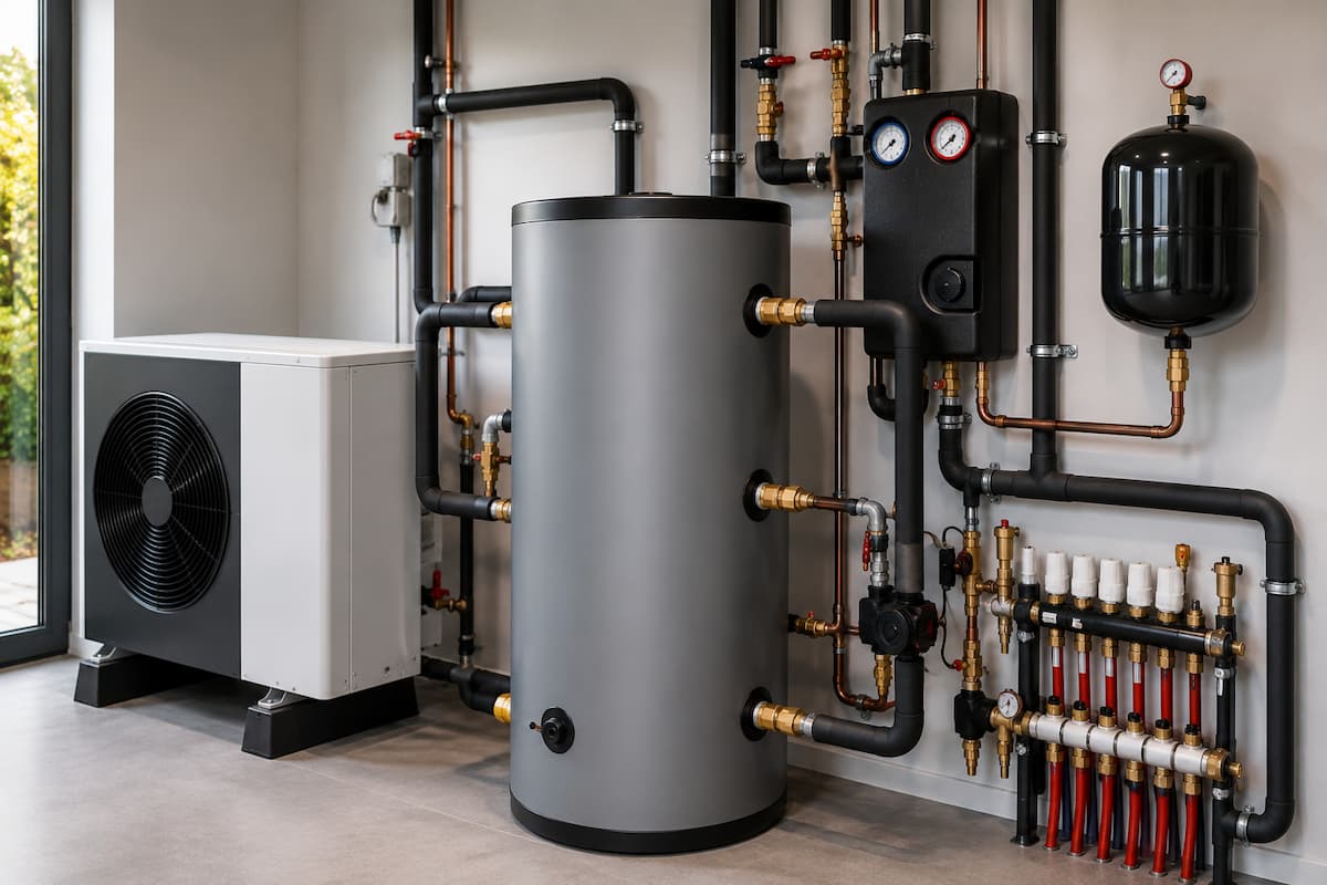
A buffer vessel is an insulated water-filled cylinder installed within the heating circuit of a heat pump system.
Unlike a domestic hot water cylinder, a buffer vessel is not intended to store usable hot water for taps or showers. Instead, it stores heated water from the system that circulates within the central heating circuit.
Its primary functions are to:
- Increase system water volume
- Improve hydraulic stability
- Reduce compressor cycling
- Support consistent flow rates
- Separate hydraulic circuits where required
Depending on the system design, a buffer vessel may perform one or several of these functions simultaneously.
Understanding its purpose within the specific installation is far more important than simply following a standard installation practice.
Buffer Vessel Or Thermal Store
Buffer vessels and thermal stores are sometimes confused, but they perform different roles.
A buffer vessel stores heating system water to improve hydraulic performance and increase system volume.
A thermal store stores heat energy for use by multiple heat sources and may also contribute to domestic hot water production via heat exchangers.
| Buffer Vessel | Thermal Store |
|---|---|
| Supports heating circuit operation | Stores usable thermal energy |
| Increases system water volume | Can serve multiple heat sources |
| Improves hydraulic stability | Provides larger heat storage capacity |
| Does not supply domestic hot water directly | May contribute to domestic hot water production |
Although both contain heated water, their purpose within a renewable heating system is very different.
Buffer Vessel Functions
A buffer vessel can perform several important functions within a heat pump installation.
Increasing System Water Volume
Heat pumps operate most efficiently when sufficient water is circulating through the system.
Some installations, particularly those with smaller heating circuits or multiple zoning arrangements, may not contain sufficient water to meet the manufacturer’s minimum volume requirement.
Adding a buffer vessel increases the available system water, allowing the heat pump to operate more steadily.
Reducing Compressor Cycling
Short cycling occurs when the heat pump repeatedly starts and stops due to insufficient heating demand or insufficient available water volume.
A buffer vessel increases the system’s thermal mass, allowing the heat pump to operate for longer periods before reaching its target temperature.
This can:
- Improve efficiency
- Reduce compressor wear
- Lower electricity consumption
- Extend equipment lifespan
Improving Hydraulic Stability
Water flow through the heat pump should remain as stable as possible.
Opening or closing zone valves or thermostatic radiator valves can rapidly alter system flow rates.
A correctly installed buffer vessel helps stabilise flow conditions, allowing the heat pump to continue operating within its design parameters.
Supporting Defrost Operation
During cold weather, air source heat pumps periodically enter a defrost cycle to remove ice from the outdoor heat exchanger.
A buffer vessel can provide additional stored heat during this process, helping maintain stable operation while the system temporarily reverses its refrigeration cycle.
Not every system requires this additional support, but it can be beneficial in certain installations.
Hydraulic Separation
Some installations require that the heat pump circuit and the heating distribution circuit operate independently.
A buffer vessel can provide hydraulic separation, allowing each circulation pump to operate without affecting the other.
This is particularly useful where:
- Multiple heating zones exist.
- Different flow requirements are present.
- Mixed heating emitters are installed.
- Larger systems require independent pump control.
Minimum System Water Volume
One of the main reasons buffer vessels are specified is to achieve the minimum system water volume recommended by the heat pump manufacturer.
Every heat pump has a minimum water content requirement to ensure stable operation.
If the available water volume is too low, the system may:
- Reach target temperature too quickly.
- Switch off prematurely.
- Restart repeatedly.
- Reduce compressor efficiency.
- Experience increased wear.
The required volume varies between manufacturers and heat pump models.
Typical examples may resemble the following.
| Heat Pump Capacity | Example Minimum System Volume |
|---|---|
| 5 to 7kW | Approximately 50 to 70 litres |
| 8 to 10kW | Approximately 80 to 100 litres |
| 12 to 16kW | Approximately 120 to 150 litres |
| 16kW and above | Manufacturer specific |
These figures are examples only. Installers should always refer to the manufacturer’s technical documentation for the specific heat pump being installed.
Buffer Vessels and Hydraulic Separation
One of the most important applications of a buffer vessel is hydraulic separation.
Without hydraulic separation, changes in the heating circuit can directly affect the flow rate through the heat pump.
For example, several thermostatic radiator valves closing simultaneously may reduce system flow below the manufacturer’s minimum requirement.
A hydraulically separated system allows the heat pump circuit to maintain its required flow rate while the secondary heating circuit responds independently to changing demand.
This improves stability throughout the installation.
| Without Hydraulic Separation | With Hydraulic Separation |
|---|---|
| Heat pump flow affected by heating circuit | Independent flow through heat pump |
| Greater risk of cycling | Improved operating stability |
| Flow varies as zones open and close | Stable primary circuit flow |
| Greater pump interaction | Reduced pump interference |
Hydraulic separation becomes increasingly valuable as system complexity increases.
Primary and Secondary Circuits
Many renewable heating systems use primary and secondary pipework arrangements.
The primary circuit carries water between the heat pump and the buffer vessel.
The secondary circuit distributes heat to the emitters throughout the property.
Separating these circuits provides several advantages.
The primary circulation pump can maintain the manufacturer’s required flow rate through the heat pump, while the secondary pump responds to the building’s heating demands.
This arrangement improves system stability and reduces unwanted interaction between circulation pumps.
Buffer Vessel Installation Positions
The position of a buffer vessel depends on the installation’s hydraulic design.
Common arrangements include:
- Two connection buffer vessels
- Four connection buffer vessels
- Return side installation
- Flow side installation
Vertical installation is generally preferred as it promotes better temperature stratification and simplifies air removal.
Installers should also consider:
- Pipe insulation
- Sensor positioning
- Drain valves
- Air vents
- Maintenance access
Poor installation can reduce the benefits that the buffer vessel is intended to provide.
Buffer Vessel Sizing
Selecting the correct buffer vessel size involves more than matching it to the heat pump output.
Installers should consider:
- Heat pump capacity
- Minimum manufacturer water volume
- Existing system volume
- Number of heating zones
- Underfloor heating circuits
- Radiator water content
- Defrost requirements
- Hydraulic separation requirements
A larger buffer vessel is not always better.
Oversized vessels may increase standing heat losses, occupy unnecessary space and increase installation costs without delivering additional performance benefits.
| Heat Pump Output | Typical Buffer Vessel Size |
|---|---|
| 5 to 8kW | 25 to 50 litres |
| 8 to 12kW | 50 to 100 litres |
| 12 to 16kW | 100 litres or greater |
These figures should be treated as general guidance only. Final sizing should always be based on the manufacturer’s recommendations and the hydraulic requirements of the individual heating system.
Buffer Vessels Versus Volumisers
One of the most common areas of confusion among installers is the difference between a buffer vessel and a volumiser. Although both increase the volume of water within the heating system, they perform different functions.
A volumiser is designed solely to increase system water content. It does not provide hydraulic separation and is generally installed in series with the heating circuit.
A buffer vessel can increase system water volume, but it can also hydraulically separate the primary and secondary circuits where required.
Understanding the difference allows installers to specify the correct component rather than adding a buffer vessel where a volumiser would be more appropriate.
| Buffer Vessel | Volumiser |
|---|---|
| Increases system water volume | Increases system water volume |
| Can provide hydraulic separation | No hydraulic separation |
| Can separate primary and secondary circuits | Installed directly within the heating circuit |
| Suitable for complex hydraulic systems | Suitable where only additional water volume is required |
| Normally uses four or two connections | Normally two connections |
The decision should always be based on the hydraulic requirements of the installation rather than personal preference.
Buffer Vessels With Radiator Systems
Many retrofit heat pump installations continue to use radiators as the primary heat emitters.
In these systems, a buffer vessel may provide several advantages, particularly where thermostatic radiator valves are fitted throughout the property.
As valves begin to close in response to room temperatures, the flow through the heating circuit changes continuously.
Without adequate system volume or hydraulic separation, these changes may affect heat pump performance.
A correctly designed buffer vessel can:
- Stabilise flow rates
- Reduce compressor cycling
- Improve system response
- Assist with hydraulic balancing
- Maintain minimum flow requirements
However, if the radiator system already provides sufficient water volume and stable circulation, a buffer vessel may not be necessary.
Buffer Vessels With Underfloor Heating
Underfloor heating generally contains considerably more water than traditional radiator systems.
This often reduces the need for additional system volume.
However, underfloor heating installations frequently include:
- Multiple manifolds
- Several heating zones
- Mixing valves
- Independent circulation pumps
These factors may make hydraulic separation desirable even where sufficient water volume already exists.
Installers should assess the complete hydraulic design before deciding whether a buffer vessel is appropriate.
Mixed Emitter Systems
Many properties now combine radiators with underfloor heating.
These systems often require different operating temperatures and different flow characteristics.
A buffer vessel can help separate these circuits while allowing each to operate under its own hydraulic conditions.
Mixed emitter systems frequently benefit from:
- Independent circulation pumps
- Stable primary flow
- Consistent heat pump operation
- Improved control of individual heating zones
This arrangement is becoming increasingly common during renovation and extension projects.
Weather Compensation Interaction
Weather compensation adjusts flow temperatures according to outdoor conditions.
A correctly installed buffer vessel should complement weather compensation rather than interfere with it.
If the buffer vessel is oversized or incorrectly connected, it may increase response times and reduce the effectiveness of weather compensation.
Installers should therefore consider:
- Sensor positioning
- System water volume
- Flow temperatures
- Hydraulic separation
- Control strategy
Correct commissioning is essential to ensure that weather compensation continues to operate as intended.
Advantages Of Buffer Vessels
When specified appropriately, buffer vessels provide several operational benefits.
These include:
- Improved hydraulic stability
- Reduced compressor cycling
- Longer compressor operating periods
- Increased system water volume
- Improved circulation
- Better support for multiple heating zones
- Easier hydraulic balancing
- Greater system flexibility
These benefits often contribute to improved reliability and lower maintenance requirements.
Potential Disadvantages
As with any component, buffer vessels should be installed only where there is a genuine engineering requirement.
Potential disadvantages include:
- Additional installation cost
- Increased plant room space
- Standing heat losses
- Additional pipework
- More complex hydraulic design
- Longer heat times if incorrectly sized
Oversized or poorly positioned buffer vessels may reduce system responsiveness without providing meaningful operational benefits.
For this reason, installers should avoid adopting a standard approach for every installation.
Installation Mistakes
Incorrect installation can significantly reduce the effectiveness of a buffer vessel.
Mistakes include:
- Incorrect pipe sizing
- Poor sensor positioning
- Insufficient insulation
- Incorrect connection arrangement
- Oversized vessels
- Undersized vessels
- Incorrect circulation pump selection
- Poor hydraulic balancing
Many of these issues become apparent only during commissioning or fault-finding.
Careful design and installation reduce the likelihood of performance problems later.
Fault Finding Buffer Vessel Problems
Although buffer vessels are relatively simple components, problems can still arise.
Installers investigating system performance should inspect:
- Water circulation
- Air accumulation
- Sensor locations
- Temperature stratification
- Pipe insulation
- Flow direction
- Hydraulic balancing
Typical symptoms include:
| Symptom | Possible Cause |
|---|---|
| Frequent compressor cycling | Insufficient system volume or incorrect hydraulic design |
| Poor heating performance | Incorrect pipe connections or balancing issues |
| High electricity consumption | Poor control strategy or excessive flow temperatures |
| Slow system response | Oversized buffer vessel |
| Temperature instability | Poor circulation or incorrect sensor placement |
These symptoms should always be investigated alongside the wider heating system rather than considering the buffer vessel in isolation.
Installation Example
Consider a four-bedroom detached property fitted with:
- A 12kW air source heat pump
- Two heating zones
- Underfloor heating downstairs
- Low temperature radiators upstairs
The property contains multiple circulation pumps and independently controlled heating zones.
Without hydraulic separation, opening and closing heating zones would continually alter the flow rate through the heat pump.
A correctly sized four-port buffer vessel provides hydraulic separation between the primary and secondary circuits.
Following commissioning, the system demonstrates:
- Stable flow rates
- Reduced compressor cycling
- Consistent room temperatures
- Improved weather compensation performance
- Efficient operation across both heating zones
This example illustrates that the buffer vessel supports the overall hydraulic design rather than acting as a standalone efficiency device.
Selecting The Correct Solution
Every installation should be assessed individually.
Questions installers should consider include:
- Does the existing system provide sufficient water volume?
- Is hydraulic separation required?
- Are multiple heating zones installed?
- Are there mixed heat emitters?
- What are the manufacturer’s minimum water volume requirements?
- Will independent circulation pumps be used?
- Does the control strategy require hydraulic separation?
Answering these questions allows the installer to determine whether a buffer vessel, volumiser or neither is the most appropriate solution.
Heat Pump Training In Staffordshire
Understanding hydraulic design is an essential part of modern renewable heating installation.
At Staffordshire Training Services, our Air Source Heat Pump Systems (Level 3), Ground Source Heat Pump Systems (Level 3) and Air and Ground Source Heat Pump Systems Combined Course (Level 3) help engineers develop the practical skills needed to design, install and commission efficient heat pump systems.
Renewables Training covers system water volume, hydraulic separation, emitter selection, weather compensation, commissioning procedures, and fault-finding, helping engineers understand how components such as buffer vessels contribute to overall system performance.
As renewable heating technology continues to evolve, a strong understanding of hydraulic design will enable installers to specify the correct components, improve efficiency, and deliver reliable, high-performing heat pump installations for their customers.
Related Articles
- Heat Pump Fault Finding For Renewable Installers
- Heat Loss Calculations for Renewable System Installers
- Heat Pump Commissioning Procedures For Renewable Installers
- Weather Compensation and Heat Pump Efficiency
- Heat Pump System Design Basics for Gas Engineers Transitioning to Renewables
Prefer an AI Summary?