Gas pipework forms the foundation of every safe gas installation. Regardless of an appliance’s quality, poor pipework design or installation can result in inadequate gas flow, excessive pressure loss, appliance malfunction, poor combustion, nuisance lockouts, and, in the most serious cases, unsafe operating conditions.
Every Gas Safe registered engineer is responsible for ensuring that gas pipework is correctly designed, installed, tested and commissioned in accordance with current legislation, recognised industry standards and manufacturer instructions. This responsibility extends beyond simply connecting appliances. It requires engineers to understand pipe sizing calculations, installation techniques, pressure loss, material selection, mechanical protection and the performance of the complete installation.
Poor workmanship remains one of the most common reasons for remedial work following inspections and ACS assessments. Undersized pipework, inadequate support, incorrect routing and poor jointing techniques continue to be identified across both domestic and commercial installations.
This examines the principles of compliant gas pipework installation, incorporating current industry guidance, practical engineering techniques, and best practices to help engineers achieve safe, efficient, and compliant installations.
Gas Pipework Regulations and Standards
Gas pipework installation is governed by legislation, British Standards, and industry procedures that together establish minimum safety requirements.
Every engineer should understand the hierarchy of these documents and apply them appropriately during design, installation and commissioning.
Gas Safety (Installation And Use) Regulations
The Gas Safety (Installation and Use) Regulations remain the primary legal framework governing gas work throughout Great Britain.
The regulations require gas installations to be:
- safely installed
- correctly maintained
- suitable for their intended purpose
- tested before being placed into service
- worked on only by competent persons
Failure to comply may result in enforcement action, prosecution or removal from the Gas Safe Register.
BS 6891
For domestic installations, BS 6891 provides detailed guidance covering:
- pipe sizing
- material selection
- installation methods
- support requirements
- testing procedures
- commissioning
It forms one of the key technical references used by domestic gas engineers.
IGEM Standards
Industry guidance published by the Institution of Gas Engineers and Managers provides further technical detail on areas including:
- gas tightness testing
- purging procedures
- gas soundness
- pressure testing
- unsafe situations
Following the publication of IGEM/UP/1B Edition 4, engineers should ensure their installation and testing procedures reflect the latest requirements.
Manufacturer Instructions
Appliance manufacturers often specify:
- minimum pipe diameters
- maximum pressure loss
- isolation arrangements
- connection methods
- commissioning procedures
Manufacturer instructions should always be followed alongside relevant standards.
Building Regulations
Where gas installation work forms part of wider building projects, engineers should also consider the requirements of the Building Regulations, particularly where pipework passes through fire-resisting elements, concealed spaces or structural components.
Pipework Design Principles
Successful gas installations begin long before the first length of pipe is installed.
Effective pipework design ensures that every appliance receives sufficient gas under all expected operating conditions while maintaining acceptable pressure loss throughout the installation.
Assessing Gas Demand
The starting point is to establish the total gas demand for the installation.
This includes:
- boiler input
- cooker demand
- fires
- water heaters
- commercial appliances
- future appliance provision where appropriate
Each appliance contributes to the overall system load.
Simultaneous Appliance Operation
Pipework should normally be designed assuming that appliances likely to operate together will do so.
For example:
- central heating boiler
- gas hob
- gas fire
All may require gas simultaneously during winter months.
Failure to account for simultaneous demand can result in pressure loss and poor appliance performance.
Pipe Routing
The chosen route should provide:
- the shortest practical pipe run
- adequate mechanical protection
- suitable access for inspection
- minimal risk of damage
- straightforward maintenance
Good routing also reduces installation costs and pressure loss.
Future Expansion
Where practical, engineers should consider future alterations.
Providing modest additional capacity can simplify future appliance upgrades without requiring complete replacement of the pipework.
Pressure Loss Considerations
Pressure loss begins at the design stage.
Every bend, elbow, tee and metre of pipe contributes resistance to gas flow.
Well-designed installations minimise unnecessary restrictions while maintaining practical installation routes.
Pipe Sizing Calculations
Correct pipe sizing is one of the most important engineering decisions made during installation.
Undersized pipework can lead to:
- appliance lockouts
- ignition failures
- incomplete combustion
- reduced efficiency
- customer complaints
Oversized pipework is generally less problematic but unnecessarily increases installation costs and material usage.
Factors Affecting Pipe Size
Pipe diameter is determined by several factors including:
- appliance heat input
- gas rate
- equivalent pipe length
- number of fittings
- operating pressure
- allowable pressure loss
These factors should always be considered together rather than individually.
Equivalent Pipe Length
Gas flow is affected not only by straight pipe runs but also by fittings.
Each fitting increases resistance.
Equivalent length calculations therefore include:
- elbows
- tees
- bends
- valves
- flexible connections where applicable
The total equivalent length provides a more realistic representation of the installation.
Worked Example One
A domestic installation contains:
- 30 kW condensing boiler
- 5 kW gas hob
Combined demand is approximately 35 kW.
The calculated equivalent pipe length is 18 metres.
Using the relevant sizing tables, the engineer selects an appropriate pipe diameter to supply both appliances while maintaining an acceptable pressure loss.
Failure to account for the combined appliance demand could result in insufficient operating pressure whenever both appliances are used simultaneously.
Worked Example Two
A boiler replacement is carried out within an older property.
The existing 15 mm pipework previously supplied a smaller appliance.
The replacement boiler has a significantly higher heat input.
Pipe sizing calculations demonstrate that the existing pipework cannot deliver the required gas flow over the installation length.
Rather than commissioning an installation that may suffer pressure loss, the engineer upgrades sections of the installation to 22 mm pipework.
Although this increases installation time, it ensures reliable appliance operation and compliance with current standards.
Pipe Sizing Reference Table
| Pipe Diameter | Typical Maximum Domestic Load | Typical Equivalent Length | Typical Application |
|---|---|---|---|
| 15 mm | Small appliance loads | Short pipe runs | Individual appliances |
| 22 mm | Medium domestic loads | Moderate pipe runs | Boilers and multiple appliances |
| 28 mm | High domestic demand | Longer installations | Larger properties |
| 35 mm and above | Commercial applications | High demand systems | Commercial installations |
Equivalent Pipe Length Reference Table
| Fitting | Typical Equivalent Length Allowance |
|---|---|
| 90° Elbow | Approximately 0.5 to 1.0 metres |
| 45° Bend | Approximately 0.3 to 0.5 metres |
| Tee Through Run | Approximately 0.6 metres |
| Tee Branch | Approximately 1.5 metres |
| Isolation Valve | Manufacturer dependent |
Engineers should always refer to current industry guidance and manufacturer data when carrying out detailed sizing calculations.
Pipe Materials
Selecting the correct pipe material is as important as choosing the correct diameter.
Material selection influences:
- durability
- corrosion resistance
- installation methods
- jointing techniques
- maintenance requirements
- long term reliability
Copper Pipework
Copper remains the most widely used material for domestic gas installations.
Advantages include:
- corrosion resistance
- ease of installation
- wide availability
- proven performance
Correct clipping and protection remain essential.
Steel Pipework
Steel pipework is commonly used where:
- larger gas volumes are required
- commercial installations are involved
- additional mechanical strength is beneficial
Threaded joints should be assembled correctly using suitable sealing compounds approved for gas installations.
Stainless Steel Corrugated Systems
Corrugated stainless steel systems provide flexibility and fewer joints.
Installation should always follow the manufacturer’s instructions regarding:
- support
- bending radius
- termination
- testing
These systems should never be treated as conventional copper installations.
Polyethylene Pipe
Polyethylene pipe is generally used for underground external gas service pipework.
Correct transition fittings should be used when connecting to metallic pipework.
Mechanical protection and installation depth remain important considerations.
Pipe Routing Requirements
The route chosen for gas pipework directly impacts safety, accessibility, maintenance, and reliability. Good routing minimises pressure loss while protecting pipework from mechanical damage and environmental deterioration.
Pipework should always be installed in a manner that allows future inspection wherever reasonably practicable.
Above Ground Pipework
Above ground installations should:
- follow practical and logical routes
- minimise unnecessary bends
- avoid vulnerable areas
- remain adequately supported
- allow access for inspection and maintenance
Pipework should never obstruct access routes or create unnecessary hazards.
Concealed Pipework
Concealed gas pipework requires careful planning.
Where pipework passes behind walls, within boxing or above ceilings, engineers should consider:
- future accessibility
- corrosion protection
- mechanical damage
- identification of pipe routes
The location of concealed pipework should be identifiable where appropriate.
Floor Voids
Pipework installed beneath suspended timber floors should:
- remain adequately supported
- avoid contact with sharp edges
- be protected against corrosion where necessary
- avoid locations where movement may occur
Adequate ventilation beneath suspended floors also helps reduce corrosion risks.
Ceiling Voids
Ceiling voids are commonly used where pipework serves upper floor appliances.
Engineers should ensure:
- pipework is clipped correctly
- joints remain accessible where required
- services do not interfere with one another
- future maintenance remains practical
Wall Cavities
Running gas pipework within wall cavities requires careful consideration.
Pipework should be protected from:
- accidental damage
- corrosion
- building movement
- fixing penetrations
Good workmanship during installation significantly reduces future risks.
Sleeving Requirements
Where gas pipework passes through walls, floors or other building elements, suitable sleeving should be provided where required.
Sleeves help:
- protect the pipework
- accommodate movement
- reduce abrasion
- assist future replacement where applicable
Appropriate sealing arrangements should also be considered in accordance with current standards.
Fire Stopping
Where pipework penetrates fire-resisting construction, suitable fire-stopping measures should be maintained.
The gas installation should not compromise the integrity of the fire compartment.
Service Risers
Pipework installed within service risers should:
- remain securely supported
- allow adequate access
- be protected from accidental damage
- avoid unnecessary congestion with other services
Careful coordination with other building services is essential.
Underground Installations
Underground pipework requires additional protection against:
- corrosion
- ground movement
- accidental excavation
- mechanical loading
Appropriate materials, installation depths and marker systems should always be used.
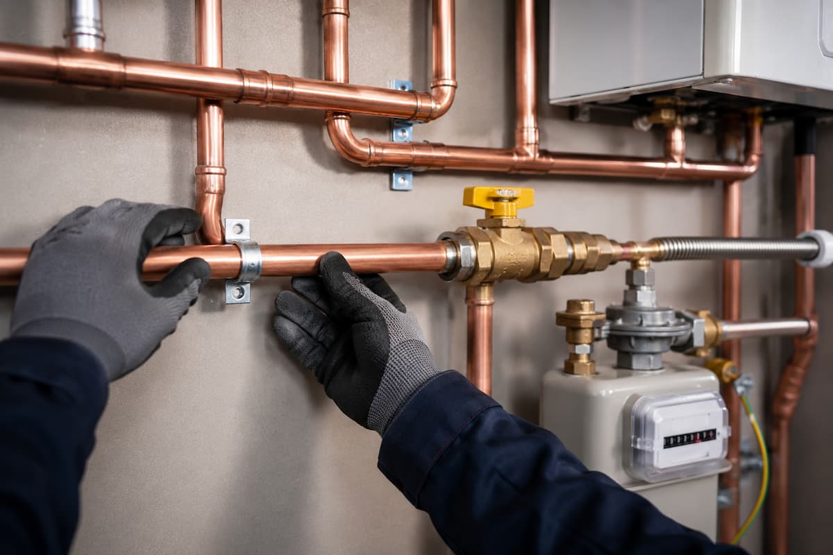
Pipe Supports and Clipping
Correct support is fundamental to maintaining the integrity of a gas installation.
Poorly supported pipework can place excessive strain on fittings, contribute to leaks and shorten the service life of the installation.
Supporting Pipework Correctly
Pipe clips should:
- support the pipe without distortion
- prevent excessive movement
- allow thermal expansion where necessary
- maintain alignment throughout the installation
Support spacing should be appropriate for both the pipe material and diameter.
Thermal Expansion
Temperature changes cause all pipe materials to expand and contract.
Although expansion within domestic gas installations is generally small, engineers should avoid creating rigid installations that prevent natural movement.
Long straight pipe runs particularly benefit from careful support positioning.
Preventing Mechanical Damage
Support arrangements should prevent pipework from:
- sagging
- vibration
- contact with sharp edges
- accidental impact
Mechanical protection may also be required where pipework passes through vulnerable locations.
Vibration Control
Vibration from boilers, commercial appliances or nearby plant can place repeated stress on joints.
Good clipping arrangements reduce movement and help maintain gas tightness throughout the installation’s life.
Pipe Support Spacing Reference Table
| Pipe Material | Nominal Diameter | Typical Horizontal Support Spacing | Typical Vertical Support Spacing |
|---|---|---|---|
| Copper | 15 mm | Approx. 1.2 m | Approx. 2.0 m |
| Copper | 22 mm | Approx. 1.8 m | Approx. 2.5 m |
| Copper | 28 mm | Approx. 2.4 m | Approx. 3.0 m |
| Steel | Various | Refer to current standards and manufacturer guidance | Refer to current standards and manufacturer guidance |
Support spacings should always be verified against current standards and manufacturer recommendations.
Pipe Jointing Methods
Reliable joints are essential to maintaining gas tightness throughout the life of an installation.
Each jointing method has specific applications, advantages and installation requirements.
Capillary Soldered Joints
Capillary soldering remains widely used for copper installations.
Successful joints depend upon:
- correct pipe preparation
- clean mating surfaces
- suitable flux
- correct heating
- complete solder penetration
Poor preparation remains one of the most common causes of defective soldered joints.
Compression Joints
Compression fittings provide a convenient alternative where heat cannot be used safely.
Advantages include:
- rapid installation
- ease of maintenance
- suitability for repair work
Engineers should ensure fittings are tightened correctly without over-tightening.
Threaded Steel Joints
Commercial installations frequently utilise threaded steel pipework.
Correct jointing requires:
- accurately cut threads
- approved sealing compounds
- correct tightening procedures
- visual inspection following assembly
Poor thread preparation may result in leakage.
Press Fit Systems
Manufacturer-approved press fit systems are becoming increasingly common.
Benefits include:
- reduced installation time
- consistent joint quality
- elimination of naked flames
Only approved tools and fittings should be used, and installation must always follow manufacturer instructions.
Inspecting Completed Joints
Following installation, joints should be inspected for:
- alignment
- mechanical integrity
- signs of distortion
- cleanliness
- accessibility for future inspection where appropriate
Final verification occurs during tightness testing.
Isolation Valves
Isolation valves allow sections of an installation or individual appliances to be safely isolated without interrupting the gas supply to the rest of the system.
Their correct selection and positioning improve maintenance, fault finding and emergency response.
Emergency Control Valve
The Emergency Control Valve remains the primary means of isolating the gas supply to the installation.
It should always:
- remain accessible
- operate correctly
- be clearly identifiable
- be free from obstruction
Appliance Isolation Valves
Individual appliance isolation valves provide additional flexibility during servicing and maintenance.
Correct positioning reduces disruption when appliances require repair or replacement.
Branch Isolation
Larger installations may benefit from strategically positioned branch isolation valves.
These allow engineers to isolate sections of pipework during:
- maintenance
- fault finding
- extensions
- alterations
Without affecting the entire installation.
Accessibility
Isolation valves should never be concealed in locations that prevent safe operation.
Access should remain available throughout the installation’s service life.
Identification
Where multiple valves exist, clear identification assists engineers during maintenance and emergencies.
Good labelling also reduces the risk of operating the incorrect valve.
Pressure Drop Requirements
Maintaining adequate operating pressure at every appliance is one of the primary objectives of gas pipework design.
Excessive pressure loss can significantly affect appliance performance and safety.
Acceptable Pressure Loss
Pipework should be designed to maintain pressure loss within the limits specified by current standards and appliance manufacturers.
Correct sizing calculations remain essential.
Appliance Performance
Insufficient operating pressure may result in:
- ignition failures
- unstable flames
- incomplete combustion
- poor heat output
- appliance lockouts
These issues frequently originate from undersized pipework rather than appliance defects.
Large Installations
Properties containing multiple appliances require careful design.
Combined gas demand and equivalent pipe length should always be considered together.
Commercial Considerations
Commercial systems often involve:
- larger gas volumes
- longer pipe runs
- multiple branches
- higher operating loads
Accurate sizing becomes even more critical.
Diagnosing Excessive Pressure Loss
Engineers investigating poor appliance performance should consider:
- undersized pipework
- excessive equivalent length
- restrictions within the installation
- faulty regulators
- partially closed valves
Pressure testing should always form part of the diagnostic process before pipework alterations are undertaken.
Protecting Pipework Against Corrosion
Corrosion remains one of the leading causes of deterioration in gas installations.
Appropriate protection significantly extends installation life and reduces future maintenance.
External Corrosion
External corrosion may result from:
- moisture
- aggressive environments
- damaged coatings
- chemical contamination
Regular inspection helps identify early signs of deterioration.
Internal Corrosion
Although less common, internal corrosion may occur under certain conditions and should not be overlooked during fault investigations.
Underground Pipework
Buried pipework requires appropriate protection through:
- suitable materials
- protective sleeving
- approved coatings
- correct installation methods
Environmental conditions should always be considered during design.
Dissimilar Metals
Direct contact between incompatible metals may accelerate corrosion.
Suitable transition fittings should always be used where different materials meet.
Inspection and Maintenance
Routine inspections should include assessment of:
- corrosion
- coating condition
- mechanical damage
- pipe supports
- evidence of environmental deterioration
Early intervention helps prevent minor defects developing into significant safety concerns.
Pipework Testing Before Commissioning
No gas installation should be commissioned until the pipework has been thoroughly inspected and tested. Testing verifies the integrity of the installation and confirms that the pipework can supply appliances safely and efficiently.
A structured commissioning process helps identify installation defects before appliances are placed into service.
Visual Inspection
Testing begins with a comprehensive visual inspection.
Engineers should confirm:
- correct pipe sizing
- suitable routing
- adequate pipe supports
- correctly assembled joints
- accessible isolation valves
- mechanical protection where required
Many installation faults can be identified before pressure testing equipment is connected.
Let By Testing
The Emergency Control Valve should be assessed to confirm it provides effective isolation.
A passing valve can affect subsequent tightness testing and may compromise the safety of the installation.
Tightness Testing
Tightness testing should be carried out in accordance with current industry procedures, including the requirements set out in IGEM/UP/1B Edition 4.
Engineers should ensure:
- correct test equipment is used
- installation volume calculations are completed where required
- pressure movement is interpreted correctly
- appliance isolation procedures are followed when applicable
Accurate testing provides confidence that the completed installation is gas tight.
Strength Testing
Certain installations may require strength testing before commissioning.
Where applicable, engineers should follow current standards and manufacturer guidance.
Purging
Following successful testing, air should be removed safely from the installation using approved purging procedures.
Correct purge calculations help minimise commissioning time while maintaining safety.
Commissioning Appliances
Only after pipework testing has been completed successfully should appliances be commissioned.
Final commissioning should include:
- operating pressure checks
- burner pressure or gas rate verification where appropriate
- combustion analysis
- operational safety checks
- documentation
Common Pipework Installation Defects
Many installation defects identified during inspections are preventable through careful planning and attention to detail.
Understanding these common issues helps engineers improve workmanship and reduce call-backs.
Undersized Pipework
Undersized pipework remains one of the most common installation defects.
Typical consequences include:
- excessive pressure loss
- appliance lockouts
- unstable combustion
- reduced efficiency
Accurate sizing calculations eliminate most of these problems.
Poor Clipping
Insufficient pipe supports may result in:
- vibration
- joint movement
- mechanical stress
- long term leakage
Correct support spacing should always be maintained.
Unsupported Meter Pipework
Poor support around meter installations can place excessive loading on:
- meter unions
- regulators
- Emergency Control Valves
This may eventually contribute to leakage or mechanical failure.
Excessive Joints
Every joint introduces another potential point of leakage.
Designed installations minimise unnecessary fittings while maintaining accessibility and serviceability.
Incorrect Routing
Poor routing can expose pipework to:
- accidental impact
- corrosion
- excessive heat
- restricted access
Installation routes should always balance practicality with safety.
Mechanical Damage
Pipework may be damaged by:
- building alterations
- fixings
- accidental impact
- vibration
- movement of surrounding structures
Visible damage should always be investigated.
Poor Sleeving
Where pipework passes through walls or floors, inadequate sleeving may lead to:
- abrasion
- corrosion
- restricted movement
Correct sleeving protects both the pipe and surrounding building fabric.
Incorrect Pipe Materials
Using unsuitable materials or incompatible fittings can reduce installation life and increase maintenance requirements.
Material selection should always comply with current standards.
Corrosion
Failure to protect pipework from environmental conditions may result in gradual deterioration and eventual gas escapes.
Routine inspection helps identify corrosion before failure occurs.
Pipework Defects Reference Table
| Defect | Likely Cause | Potential Consequence | Corrective Action |
|---|---|---|---|
| Undersized Pipework | Poor design calculations | Low operating pressure | Resize affected sections |
| Poor Clipping | Insufficient supports | Pipe movement and joint stress | Install additional supports |
| Loose Joint | Poor workmanship | Gas escape | Repair and retest |
| Mechanical Damage | Impact or building work | Reduced integrity | Assess and replace where necessary |
| Corrosion | Environmental exposure | Pipe deterioration | Replace affected pipework |
| Poor Routing | Incorrect installation planning | Damage and restricted access | Reroute pipework |
Pipework Fault Finding
Pipework defects do not always present as gas escapes. Engineers are frequently called to investigate appliance performance issues that ultimately originate within the installation pipework.
A logical fault-finding approach prevents unnecessary component replacement and reduces diagnostic time.
Low Operating Pressure
Where appliances exhibit poor performance, engineers should confirm:
- inlet working pressure
- operating pressure
- appliance demand
- gas rate
- pipe sizing
Low operating pressure often indicates excessive pressure loss within the installation.
Excessive Pressure Drop
Pressure drop may result from:
- undersized pipework
- excessive equivalent length
- restrictions
- partially closed valves
- poor installation design
Systematic testing helps identify the underlying cause.
Gas Rate Problems
Incorrect gas rates may indicate:
- inadequate gas supply
- installation restrictions
- regulator issues
- appliance faults
Pipework should always be assessed before assuming appliance failure.
Pipe Vibration
Vibration may indicate:
- poor clipping
- unsupported sections
- appliance induced movement
Correct support generally resolves these issues.
Concealed Leakage
Where Edition 4 tightness testing procedures indicate leakage remains after appliance isolation, engineers may need to investigate concealed pipework using:
- sectional testing
- electronic gas detection
- installation drawings
- visual inspection where accessible
A structured approach improves the likelihood of efficiently locating hidden defects.
Typical Pipework Design and Commissioning Workflow
The installation process should follow a logical sequence to minimise errors and ensure compliance.
1. Assess appliance demand.
2. Calculate gas rate requirements.
3. Determine equivalent pipe length.
4. Select suitable pipe diameter.
5. Choose appropriate materials.
6. Plan routing and support locations.
7. Install pipework.
8. Inspect workmanship.
9. Complete let by testing.
10. Carry out tightness testing.
11. Purge the installation.
12. Commission appliances.
13. Complete combustion analysis where applicable.
14. Record all commissioning results.
Following a consistent workflow improves quality and reduces the likelihood of omissions.
ACS Assessment Expectations
Pipework installation forms a significant element of ACS assessments because it combines design, installation and testing competence.
Knowledge Requirements
Candidates should understand:
- pipe sizing calculations
- pressure loss
- equivalent length calculations
- material selection
- routing requirements
- testing procedures
- relevant legislation
Practical Assessment Expectations
Assessments may require engineers to:
- size pipework correctly
- identify installation defects
- inspect completed installations
- explain pressure loss calculations
- justify material selection
- carry out testing procedures
Candidate Errors
Assessors frequently identify:
- incorrect pipe sizing
- poor equivalent length calculations
- inadequate support arrangements
- incorrect routing
- weak technical justification
- incomplete testing procedures
Understanding the engineering principles behind installation decisions significantly improves assessment performance.
Pipework Installation Checklist
| Inspection Item | Completed |
|---|---|
| Pipe sizing calculations completed | ☐ |
| Equivalent length assessed | ☐ |
| Correct material selected | ☐ |
| Pipe routing satisfactory | ☐ |
| Pipework adequately supported | ☐ |
| Isolation valves accessible | ☐ |
| Mechanical protection provided | ☐ |
| Corrosion protection satisfactory | ☐ |
| Visual inspection completed | ☐ |
| Let by test completed | ☐ |
| Tightness test completed | ☐ |
| Purging completed | ☐ |
| Appliances commissioned | ☐ |
| Documentation completed | ☐ |
Gas Training Courses In Staffordshire
Gas pipework installation combines design principles, practical installation techniques and regulatory compliance. Developing competence in these areas is essential for engineers carrying out new installations, system alterations, boiler replacements and commissioning work.
At Staffordshire Training Services, engineers can strengthen their knowledge through gas training, ACS assessments, reassessments and technical training covering gas installation standards, pipe sizing, tightness testing, gas soundness procedures, combustion analysis and current industry guidance.
Keeping technical knowledge up to date helps engineers confidently apply current standards, improve workmanship, and maintain compliance at every stage of a gas installation.
Achieving High Standards Of Gas Pipework Installation
Every safe gas installation begins with correctly designed and professionally installed pipework. Accurate pipe sizing, appropriate material selection, careful routing, and effective support all contribute to reliable appliance operation and installation integrity.
By combining sound engineering principles with thorough testing and commissioning procedures, engineers can minimise pressure loss, reduce future faults and maintain compliance with current legislation and recognised industry standards.
Ultimately, quality pipework installation is not simply about connecting appliances. It provides the foundation for gas safety, efficient appliance performance and customer confidence, making it one of the most important skills every Gas Safe registered engineer should continue to develop throughout their career.
Related Articles
- Gas Pressure Testing and Appliance Performance For Engineers
- Gas Tightness Testing Fault-Finding Techniques
- Gas Pressure, Flow, Tightness Testing and Purging Explained
- Unsafe Situations and Gas Engineer Legal Duties
- Standards Of Workmanship and Industry Compliance For Gas Engineers
Prefer an AI Summary?