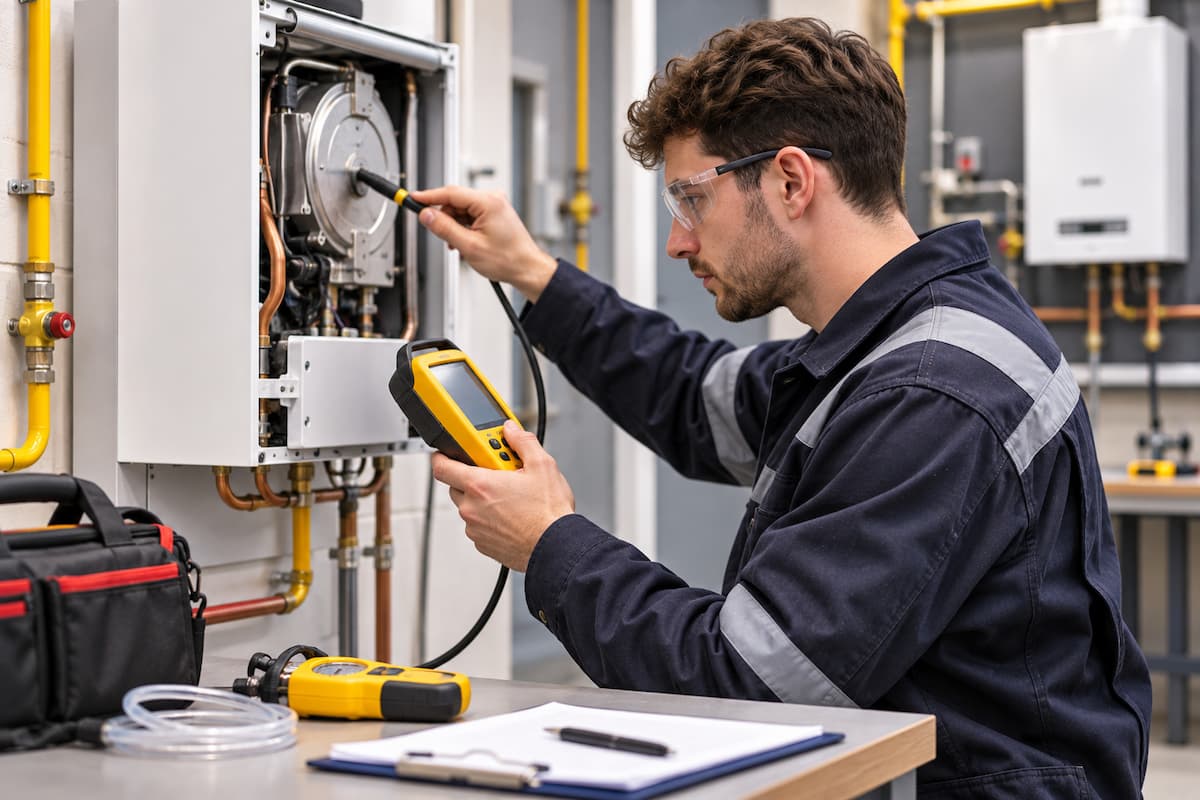
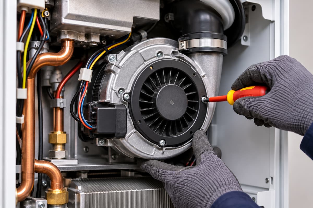
A gas boiler fan plays an essential role in the safe operation of modern room-sealed appliances. It helps establish the combustion air supply and supports the movement of combustion products through the appliance and flue system. If the fan fails to operate correctly, the boiler may prevent ignition, interrupt burner operation or enter a fault condition.
However, a boiler displaying a fan or airflow fault does not necessarily have a defective fan. Problems with electrical supplies, electronic control signals, fan speed feedback, restricted air intake or flue arrangements can produce similar symptoms.
For gas engineers, effective fault finding involves establishing the expected operating sequence, confirming electrical and mechanical fan operation, interpreting diagnostic information and checking the appliance against the manufacturer’s instructions.
Modern fan assemblies can incorporate electronically controlled motors, integrated circuit boards and speed feedback systems. This makes diagnosis more involved than simply checking whether the motor receives a mains voltage supply.
The engineer must also recognise that fan operation is closely connected to the boiler’s ignition and combustion control systems. The relationship between airflow, gas delivery and flame supervision is central to safe appliance operation.
This article examines gas boiler fan operation, airflow monitoring, electrical testing, fault diagnosis and the checks required following repairs.
Gas Boiler Fan Operation
In a modern fan-assisted gas boiler, the fan provides the pressure difference required to move combustion air through the appliance and discharge combustion products through the designed flue route.
The precise arrangement depends on the boiler and its combustion system. Most modern domestic condensing boilers use a fan within a room-sealed combustion arrangement, with the fan forming part of a controlled combustion process.
The fan may perform several functions:
- Support the supply of combustion air to the burner.
- Provide the pressure difference needed to overcome appliance and flue resistance.
- Operate during prepurge and other manufacturer operating stages.
- Support the correct combustion conditions during burner operation.
- Respond to modulation commands from the boiler PCB.
- Provide speed or operating feedback to the control system.
The relationship between airflow and gas delivery is particularly important in premix combustion systems. These appliances are designed to maintain suitable combustion conditions across their operating range through an arrangement of fan control, gas valve operation and combustion components.
The fan cannot be assessed independently of the wider combustion system. A motor may rotate correctly while the appliance experiences an airflow restriction, incorrect fan speed or a combustion fault.
Types Of Boiler Fans
The design and control arrangement of a boiler fan influence the diagnostic procedures available to the engineer.
Conventional AC Fans
Some older fan-assisted appliances use relatively straightforward AC motor arrangements.
The fan may receive a switched mains supply when the appliance requires it to operate. The control system may use an air pressure switch or another proving arrangement to establish that the required operating condition has been achieved.
Fault diagnosis may involve checking the motor supply, wiring, mechanical condition and relevant proving components.
The engineer must still follow the appliance manufacturer’s instructions, particularly where the fan operates as part of a safety sequence.
Electronically Controlled Fans
Modern condensing boilers frequently incorporate electronically controlled fan motors.
These may use brushless motor technology with integrated electronics that regulate fan speed in response to commands from the boiler PCB.
Depending on the appliance, the fan may receive a permanent electrical supply alongside a separate electronic control signal.
Fan speed can change as the burner modulates, allowing the appliance to operate across its designed heat output range.
A fan running at different speeds during normal boiler operation is therefore not necessarily displaying a fault.
Premix Boiler Fans
In premix combustion systems, the fan forms part of an arrangement that supplies a controlled mixture of gas and air to the burner.
The precise gas and air control method varies between manufacturers.
Some appliances use pneumatic gas and air ratio control, while others incorporate electronically controlled gas valve arrangements and additional combustion monitoring.
Incorrect fan performance can affect the combustion process, but the resulting symptoms must be investigated alongside the gas valve, air intake, flue and appliance control system.
Fan replacement or adjustment must not be used as a substitute for identifying the underlying cause of a combustion problem.
Boiler Fan Operating Sequence
Understanding the appliance operating sequence is one of the most useful diagnostic techniques available to gas engineers.
A typical modern boiler may follow a sequence involving:
- Central heating or domestic hot water demand is received.
- The PCB checks the relevant operating and safety conditions.
- The fan receives an operating command.
- The fan reaches the required operating condition.
- Any applicable airflow or fan speed proving requirements are satisfied.
- The appliance proceeds through its ignition sequence.
- Burner operation is established and monitored.
- The fan responds to the required burner output and operating conditions.
This is an illustrative sequence. The actual order, proving arrangements and timing depend on the appliance design.
An engineer should not assume that every boiler uses an air pressure switch, or that fan operation is proved in the same way across different manufacturers.
A boiler that fails before ignition requires a different diagnostic approach from an appliance that ignites successfully but subsequently loses fan speed feedback.
The relationship between fan operation, ignition commands and burner establishment is examined in gas boiler ignition fault finding, where identifying the point of failure helps distinguish electrical, ignition and combustion faults.
Fan Electrical Supply and Control
Electrical diagnosis begins by identifying the fan type and the control arrangement shown in the manufacturer’s wiring diagram.
Depending on the appliance, the fan may incorporate:
- Permanent or switched mains electrical supply.
- Separate low voltage control connections.
- Pulse width modulation control.
- Fan speed feedback.
- Integrated motor electronics.
- Dedicated communication connections.
These arrangements cannot be tested using a single universal procedure.
A fan receiving 230 V does not necessarily mean that it has received a valid command to rotate. Equally, an absent mains supply may be normal if the boiler is not currently requesting fan operation.
Engineers should establish the expected supply and command conditions before interpreting measurements.
Electrical Supply Testing
Where the manufacturer specifies electrical supply testing, the engineer should confirm the expected voltage at the appropriate point in the circuit.
Possible electrical faults include damaged wiring, poor connections, defective PCB outputs and internal motor failures.
The absence of voltage at the fan should not automatically be interpreted as a failed PCB. The control system may be deliberately withholding the supply because the required operating conditions have not been satisfied.
Similarly, correct voltage at the motor terminals does not establish that the motor electronics or mechanical components are functioning correctly.
Electrical testing must be carried out using suitable equipment and appropriate safe isolation procedures. Live measurements should only be undertaken where necessary, by competent persons and in accordance with the manufacturer’s instructions.
The principles of boiler electrical fault finding are particularly relevant because modern fan assemblies often contain both mains and electronic control circuits.
Pulse Width Modulation
Pulse width modulation, commonly abbreviated to PWM, is one method used to control electronically operated boiler fans.
A PWM signal consists of pulses that vary in duration relative to the overall signal period.
The duty cycle describes the proportion of each period during which the signal is active.
For example, a 40% duty cycle means the signal is active for 40% of each complete period.
However, the relationship between duty cycle and fan speed is manufacturer-dependent. A particular duty cycle must not be assumed to represent the same fan speed or operating command across different appliances.
Testing PWM circuits requires knowledge of the expected signal characteristics and the manufacturer’s specified procedure.
An ordinary multimeter may not provide enough information to assess the signal accurately. Where appropriate, a suitable meter with duty cycle measurement or an oscilloscope may be required.
Engineers must avoid applying external voltages or test signals to electronic control terminals unless explicitly permitted by the manufacturer.
Fan Speed Feedback and Hall Sensors
Many electronically controlled boiler fans provide operating information to the PCB.
This may include fan speed feedback or a signal indicating the motor’s operating condition.
Some designs use Hall effect sensing as part of the motor’s electronic control or speed detection arrangement.
A Hall effect sensor responds to a magnetic field and can be used to detect changes associated with motor rotation.
The control system may use the resulting information to monitor whether the fan is operating within its expected range.
Fan Speed Feedback Faults
A boiler may identify a fault if the fan fails to reach the required speed, operates outside an expected range or provides invalid feedback.
Possible causes include:
- Fan motor failure.
- Defective integrated fan electronics.
- Damaged wiring or connectors.
- Missing or incorrect control signals.
- Faulty speed feedback circuitry.
- Mechanical resistance affecting fan rotation.
- Airflow or flue conditions affecting fan loading.
A fan speed fault code does not automatically identify the fan assembly as defective.
The engineer should compare the appliance’s requested fan operation with the actual fan response and any available diagnostic information.
Interpreting Fan Speed Data
Some boilers provide fan speed information through their service menus.
Depending on the manufacturer, this may include requested speed, actual speed or diagnostic values associated with fan operation.
Fan speed is commonly expressed in revolutions per minute (rpm).
Where both requested and actual speeds are available, the difference can provide useful diagnostic evidence.
For example, if the control system requests an increase in fan speed but the reported speed remains unchanged, the engineer may investigate the motor, electronic control and feedback circuits.
However, the displayed values must be interpreted against manufacturer specifications. A difference between requested and actual speed during a transient operating condition does not necessarily indicate a fault.
Air Pressure Switches and Airflow Monitoring
Some fan-assisted gas appliances use an air pressure switch to prove that the required pressure condition has been established before allowing ignition.
An air pressure switch responds to a pressure difference or pressure condition, depending on its design.
It may be connected to the appliance through pressure sensing tubes and associated connections.
When the fan operates, the resulting pressure condition can cause the switch to change state.
The boiler control system then uses this information as part of its operating sequence.
However, an air pressure switch does not directly measure the complete combustion air flow rate. It proves a specified pressure condition at the sensing points.
Modern boilers may instead use fan speed feedback, electronic monitoring or other manufacturer arrangements.
Air Pressure Switch Faults
Where an appliance incorporates an air pressure switch, potential problems include:
- Defective switch contacts.
- Damaged or disconnected sensing tubes.
- Blocked pressure sensing points.
- Moisture within sensing tubes.
- Incorrect pressure conditions.
- Wiring faults.
- Restricted air intake or flue arrangements.
The engineer should establish whether the expected pressure condition is present before identifying the switch as defective.
A switch that does not change state may be responding correctly to inadequate fan performance or a restricted air path.
Safety proving devices must never be bypassed to permit appliance operation.
Differential Pressure Testing
Where manufacturer procedures permit, a suitable differential pressure instrument can be used to assess pressure conditions at specified test points.
Differential pressure is the difference between two measured pressures:
Δp = p₁ − p₂
Where:
- Δp = differential pressure
- p₁ = pressure at the first measurement point
- p₂ = pressure at the second measurement point
For example, if one test point measures 80 Pa and the second measures 20 Pa, both relative to the same reference:
Δp = 80 − 20 = 60 Pa
This is a calculation example rather than a boiler operating specification.
Actual pressure requirements vary considerably between appliances and must be obtained from manufacturer documentation.
Pressure measurements should never be used to justify adjustment of a safety device outside its specified settings.
Flue and Air Intake Restrictions
The fan must overcome the resistance created by the appliance’s internal air and combustion product pathways and the connected flue arrangement.
Restricted airflow can affect fan performance, combustion conditions and appliance safety.
Potential causes include:
- Blocked or obstructed flue terminals.
- Restrictions within the air intake route.
- Incorrectly assembled flue components.
- Damaged or displaced flue seals.
- Excessive or unsuitable flue arrangements.
- Internal combustion product pathway restrictions.
- Condensate related obstructions.
A fan may rotate and provide valid speed feedback while the appliance still experiences inadequate airflow.
This distinction is important because electronic fan monitoring does not establish that every part of the combustion air and flue system is unobstructed.
The requirements for ventilation and flueing of gas appliances must be considered alongside the manufacturer’s permitted flue configuration, terminal position and combustion air arrangements.
Blocked Flue Terminals
External terminals can become obstructed by debris, vegetation, nesting material or other objects.
An obstruction may affect the appliance’s ability to maintain the intended airflow and combustion conditions.
Depending on the appliance, this may produce an ignition failure, fan fault, combustion problem or safety shutdown.
Engineers should inspect accessible terminal arrangements where appropriate and establish whether the flue system remains suitable for continued operation.
Flue Installation Defects
Incorrect flue installation can affect appliance performance even when the fan and electronic controls are functioning correctly.
Potential defects include unsuitable flue lengths, incorrect components, inadequate support and problems with joint assembly or sealing.
The permitted configuration depends on the appliance manufacturer and the approved flue system.
Engineers should not assume that an installation is acceptable simply because the appliance ignites and operates.
Condensate Related Restrictions
Condensing boilers produce condensate during normal operation.
The appliance and its condensate drainage arrangement must allow condensate to discharge as intended.
Blocked condensate traps, frozen external condensate pipework or drainage restrictions can affect appliance operation.
Depending on the boiler design, condensate accumulation may interfere with the combustion product pathway or trigger an appliance fault.
A fan-related symptom may therefore require inspection of the condensate arrangement rather than immediate replacement of the fan.
Fan Performance and Combustion
The relationship between fan operation and combustion is particularly important in modern premix boilers.
Fan speed may influence the air and gas mixture delivered to the burner, although the exact relationship depends on the combustion control arrangement.
Incorrect airflow can contribute to unsuitable combustion conditions, potentially affecting carbon monoxide production, carbon dioxide readings and appliance efficiency.
However, combustion performance cannot be assessed reliably from fan speed alone.
A fan may operate at its requested speed while another component or restriction affects the combustion process.
Similarly, an abnormal combustion reading does not automatically identify a fan fault.
The engineer should consider the complete combustion system, including the fan, air intake, gas valve, burner, heat exchanger and flue.
Combustion Analysis
Following relevant repairs, combustion performance may need to be checked using a suitable flue gas analyser.
The required procedure depends on the appliance and the work completed.
The manufacturer’s instructions determine the operating conditions, test points, permitted values and any authorised adjustment procedures.
Accurate combustion analysis and flue gas testing are essential where the work affects the appliance’s combustion system.
Fan replacement on a premix boiler may require specific checks to confirm that combustion remains within the manufacturer’s limits.
Engineers should not adjust gas and air ratio settings without the necessary competence, equipment and manufacturer procedures.
Fan Fault Codes and Diagnostic Data
Modern boilers use diagnostic codes to identify conditions detected by their control systems.
A fan code may indicate that the appliance has detected a problem with fan operation, speed control, electronic feedback or the expected operating sequence.
However, a fault code describes the condition recognised by the PCB. It does not necessarily identify the component responsible.
For example, a fan speed fault may result from a defective motor, but it could also involve wiring, electronic control or a mechanical restriction.
Similarly, an airflow proving fault may originate from the pressure sensing arrangement rather than the fan itself.
Interpreting Diagnostic Information
Where available, engineers should examine:
- Current appliance fault codes.
- Stored fault history.
- Requested fan operating status.
- Requested fan speed.
- Actual or reported fan speed.
- Relevant airflow proving information.
- Burner operating status.
- Ignition sequence information.
- Combustion related diagnostic values.
These readings should be compared with the appliance’s physical operation and the manufacturer’s technical information.
Repeatedly resetting a boiler without investigating the fault can remove useful diagnostic evidence and may expose the appliance to repeated unsuccessful operating attempts.
Gas Boiler Fan Fault Diagnosis Table
The following table summarises typical symptoms and the areas engineers may need to investigate.
| Reported Symptom | Possible Cause | Diagnostic Direction |
|---|---|---|
| Fan does not start | Electrical supply, control signal, motor or PCB fault | Check the expected operating command, supply, wiring and fan condition |
| Fan runs but boiler does not ignite | Airflow proving, ignition control or another safety condition | Identify the stage at which the operating sequence stops |
| Fan speed fault displayed | Motor, control signal, speed feedback or mechanical problem | Compare requested and reported fan operation |
| Fan operates intermittently | Electrical connection, motor electronics or operating condition | Investigate the fault under the conditions in which it occurs |
| Air pressure switch does not change state | Insufficient pressure difference, sensing tube or switch fault | Check the manufacturer’s pressure conditions and sensing arrangement |
| Boiler ignites then shuts down | Combustion, flame supervision, fan feedback or another control fault | Establish whether the shutdown follows loss of flame, airflow or another monitored condition |
| Abnormal combustion readings | Airflow restriction, gas and air control problem or combustion component defect | Assess the complete combustion system using manufacturer procedures |
| Fan noisy or vibrating | Mechanical wear, foreign material or mounting problem | Inspect the fan assembly and associated components |
Practical Fan and Airflow Fault Scenarios
The following scenarios illustrate the importance of separating electrical faults, fan operation, airflow restrictions and combustion control problems.
Scenario One: Fan Does Not Start
A boiler receives a central heating demand, but the fan does not operate, and the burner fails to ignite.
The engineer confirms that the appliance has reached the stage at which the fan should start.
The manufacturer’s information identifies the expected electrical supply and control arrangement.
If the required supply or command is absent, investigation should focus on the wiring, PCB output and any operating conditions preventing fan activation.
If the correct supply and command are present, the fan motor, integrated electronics and mechanical condition become the main areas of investigation.
The fan should not be replaced until the engineer has established that the correct operating conditions are present.
Scenario Two: Fan Runs, But Boiler Does Not Ignite
A boiler receives a heating demand, and the fan begins operating. However, ignition does not take place.
The engineer establishes whether the fan reaches its required operating condition and whether the appliance recognises the expected proving information.
If the fan operates correctly and its required conditions are satisfied, the investigation should move to the next stage of the appliance’s operating sequence.
Depending on the boiler, this may involve ignition control, gas valve operation or another safety requirement.
The operation of gas safety devices and flame supervision systems is relevant when establishing whether the appliance has prevented ignition or interrupted burner operation for safety reasons.
Scenario Three: Fan Speed Feedback Fault
A modern condensing boiler displays a fan speed fault.
The fan can be heard operating, but the appliance fails to proceed through its normal sequence.
Service information indicates that the requested fan speed and reported speed do not agree.
The engineer checks the fan’s electrical connections, control arrangement and feedback information using the manufacturer’s procedures.
The investigation must establish whether the fan is genuinely operating at an incorrect speed or whether the feedback circuit is providing inaccurate information.
Audible fan operation alone does not prove that the motor is functioning within its specified operating range.
Scenario Four: Boiler Operates Then Shuts Down
A boiler ignites successfully and operates for a short period before shutting down.
The fan continues operating during part of the sequence, but the appliance subsequently records a fault.
The engineer examines the stored fault information and identifies the stage at which operation is interrupted.
Possible areas of investigation include fan speed feedback, combustion conditions, flame supervision and other appliance safety controls.
A shutdown occurring after successful ignition should not automatically be treated as a fan failure.
The engineer must establish which operating condition the control system has detected as abnormal.
Scenario Five: Intermittent Fan Operation
A boiler operates normally when cold but develops a fan fault after extended operation.
Possible causes include temperature-affected electronic components, intermittent wiring connections or a developing motor fault.
The engineer should establish whether the fault is associated with a particular operating temperature, fan speed or appliance demand.
Where safe and permitted by the manufacturer, relevant measurements should be taken under the conditions that reproduce the fault.
A fan that operates correctly during an initial test may still have an intermittent defect that only becomes apparent during prolonged operation.
Scenario Six: Airflow Restriction Mistaken For Fan Failure
A boiler displays an airflow fault and fails to complete its normal operating sequence.
The fan can be heard running, but the required airflow proving condition is not achieved.
Inspection identifies an obstruction affecting the appliance’s air intake or flue arrangement.
The engineer addresses the restriction in accordance with the manufacturer’s instructions and carries out the required checks before returning the appliance to service.
This scenario demonstrates that a functioning fan motor does not guarantee adequate airflow through the appliance.
Fan and Airflow Diagnostic Workflow
A structured diagnostic process helps engineers avoid unnecessary component replacement.
Confirm Reported Symptoms and Fault History
↓
Identify Appliance Operating Sequence
↓
Establish Fan Command and Operating Status
↓
Does The Fan Operate As Expected?
If no:
↓
Investigate Electrical Supply, Control Signals, Wiring, Motor and Mechanical Condition
If yes:
↓
Assess Fan Feedback, Airflow Proving, Flue Conditions and Combustion Requirements
↓
Identify and Correct The Underlying Cause
↓
Recommission And Verify Appliance Safety
The diagnostic process should always be adapted to the appliance manufacturer’s procedures.
The objective is to establish whether the fault originates from the fan, its electrical control, the airflow pathway or another part of the appliance operating sequence.
Repair and Recommissioning
After identifying and correcting a fan or airflow fault, the engineer must verify that the appliance operates safely and that the original problem has been resolved.
The required checks depend on the repair, appliance design and manufacturer instructions.
These may include:
- Confirming the fan is correctly installed and secured.
- Checking electrical connections and wiring.
- Verifying fan operation and electronic control.
- Checking fan speed feedback where applicable.
- Confirming any required airflow proving conditions.
- Inspecting relevant air intake and flue components.
- Checking disturbed seals and connections.
- Confirming correct ignition and burner operation.
- Carrying out required combustion checks.
- Verifying correct operation across relevant appliance modes.
- Checking for fault codes after recommissioning.
- Completing the necessary safety checks and records.
Fan Replacement
Replacement fans must be suitable for the exact appliance model and specification.
Components that appear physically similar may have different motor characteristics, control arrangements or operating requirements.
Engineers should use manufacturer replacement components and follow the specified installation procedures.
On premix boilers, replacing a fan may affect components within the combustion air and gas delivery arrangement.
Any disturbed seals, connections or associated components must be restored correctly, and combustion checks completed as specified by the manufacturer.
Unsafe Appliance Conditions
If an engineer identifies a condition that makes the appliance unsafe, the appropriate gas industry unsafe situations procedures must be followed.
This is particularly important where faults involve damaged flue components, combustion product leakage, inadequate combustion air supply or unsafe combustion performance.
The principles governing unsafe situations and gas engineer legal duties apply when assessing whether an appliance can remain in service.
A boiler must not be returned to operation simply because a fault code has cleared. The underlying defect must be resolved and the required safety checks completed.
ACS Assessment Considerations
Fan and airflow fault diagnosis requires engineers to combine knowledge of appliance operating sequences, electrical testing, combustion principles and safety controls.
Engineers preparing for assessment should be able to distinguish between a failed component and a correctly functioning safety system responding to an abnormal condition.
Important principles include recognising that:
- A fan fault code does not necessarily mean the fan is defective.
- Electrical supply alone does not prove that an electronically controlled fan has received the correct command.
- Fan rotation does not confirm adequate airflow.
- Air pressure switches prove specified pressure conditions rather than directly measuring total airflow.
- Fan speed feedback must be interpreted using manufacturer information.
- Combustion performance cannot be established from fan operation alone.
- Safety devices must never be bypassed to allow appliance operation.
Practical fault finding should demonstrate the ability to follow a logical diagnostic process, select appropriate testing methods and recognise the limits of an engineer’s competence.
The precise knowledge and practical tasks assessed depend on the relevant qualification and assessment specification.
Fan and Airflow Inspection Checklist
The following checklist can support a structured approach to appliance diagnosis. It does not replace the manufacturer’s service and safety procedures.
| Diagnostic Stage | Completed |
|---|---|
| Customer reported symptoms confirmed | ☐ |
| Manufacturer instructions consulted | ☐ |
| Appliance fault history checked | ☐ |
| Heating or hot water demand confirmed | ☐ |
| Expected fan operating sequence identified | ☐ |
| Fan type and control arrangement identified | ☐ |
| Electrical supply checked where required | ☐ |
| Electronic control signals assessed where applicable | ☐ |
| Fan mechanical condition assessed | ☐ |
| Fan speed feedback checked where available | ☐ |
| Airflow proving arrangement assessed where fitted | ☐ |
| Air intake and flue conditions checked | ☐ |
| Condensate drainage considered where relevant | ☐ |
| Ignition and burner operation assessed | ☐ |
| Underlying fault established before replacement | ☐ |
| Repair completed to manufacturer requirements | ☐ |
| Required combustion checks completed | ☐ |
| Appliance operation verified | ☐ |
| Relevant safety checks and records completed | ☐ |
Gas Training Courses In Staffordshire
Modern gas boiler fault finding requires more than recognising fault codes or replacing components. Engineers must understand the relationship between electrical control, airflow, ignition, combustion and appliance safety.
At Staffordshire Training Services, we provide accredited gas training in Stafford for new entrants and experienced engineers developing their technical knowledge and practical competence.
Our Gas Managed Learning Programme provides a structured route into domestic gas engineering, combining technical training, practical experience and progression towards ACS assessment.
For engineers working with electrical components such as fan motors, PCBs, sensors and electronic controls, our Safe Isolation of Electrical Installations Course supports the safe working practices needed before electrical inspection and testing.
Developing a systematic approach to fault finding helps engineers distinguish genuine component failures from control or installation problems, reducing unnecessary repairs while maintaining appliance safety.
Related Articles
- Boiler Electrical Fault Finding For Gas Engineers
- Gas Boiler Ignition Fault Finding For Gas Engineers
- Gas Safety Devices and Flame Supervision Systems for Gas Engineers
- Combustion Analysis and Flue Gas Testing For Gas Engineers
- Ventilation and Flueing Requirements For Gas Appliances
Prefer an AI Summary?