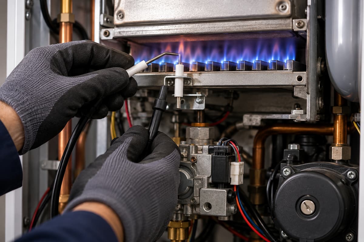
A gas boiler that fails to ignite can present engineers with several different faults that produce the same result for the customer. The appliance may remain silent, begin its operating sequence but produce no spark, spark without establishing a flame, light briefly before locking out or operate intermittently.
Effective ignition fault finding therefore involves more than checking an ignition electrode or replacing a component associated with a fault code. Modern boilers combine electrical controls, sensors, gas valves, fans, ignition components, burner assemblies and flame supervision systems within a controlled operating sequence.
An ignition related lockout can originate from the electrical system, gas supply, combustion system, safety controls or flame proving circuit. Effective boiler electrical fault finding helps establish whether the appliance has received the correct inputs and produced the expected outputs before attention moves to individual ignition components.
The key is to establish exactly where the operating sequence stops, then test the components and conditions associated with that stage.
The Boiler Ignition Sequence
Although designs vary between manufacturers and appliance types, a boiler normally requires several conditions to be satisfied before the PCB permits burner ignition.
Manufacturer technical information should always determine the exact sequence for the appliance being tested, but a simplified sequence may look like this:
Heat or hot water demand
↓
Required safety conditions confirmed
↓
Pump or fan operates where required
↓
Airflow or fan operation proved
↓
Ignition system energised
↓
Gas valve energised
↓
Gas reaches burner
↓
Spark ignites gas and air mixture
↓
Flame established
↓
Flame proved
↓
Burner continues operating
A fault at any stage can prevent the sequence progressing.
An appliance producing no spark may have an ignition circuit fault, but the PCB could also be deliberately withholding ignition because an earlier condition has not been satisfied.
Before testing the ignition system, the engineer should establish whether the boiler has actually reached the ignition stage.
Establishing The Point of Failure
Following the sequence prevents an ignition lockout from becoming an instruction to start replacing ignition components.
Consider three boilers displaying similar ignition symptoms.
The first never operates its fan.
The second operates the fan and produces a spark, but no burner flame appears.
The third establishes a burner flame, then shuts down several seconds later.
The customer might describe all three as a boiler that will not light, yet each takes the engineer into a different diagnostic area.
The investigation should establish:
- whether demand has been recognised
- which components operate
- whether the required safety conditions are satisfied
- whether a spark is produced
- whether the gas valve receives the required command
- whether gas reaches the burner
- whether flame is established
- whether flame is subsequently proved
This reduces a broad ignition complaint to a specific stage within the operating sequence.
Ignition Fault Categories
The behaviour of the appliance provides useful evidence before electrical or gas measurements begin.
| Boiler Behaviour | Diagnostic Area | Initial Engineer Focus |
|---|---|---|
| Sequence does not reach ignition | Earlier permissive or control condition | Demand, sensors, fan, safety controls and PCB inputs |
| Ignition stage reached but no spark | Ignition circuit | PCB output, ignition generator, lead and electrode |
| Spark present but no flame | Ignition position or gas delivery | Spark quality, gas valve operation and gas supply |
| Flame establishes then disappears | Flame proving or combustion | Flame signal, earth path, polarity and flame stability |
| Delayed ignition | Ignition or combustion condition | Electrode position, burner condition, gas and air delivery |
| Intermittent ignition failure | Electrical, mechanical or combustion fault | Operating sequence under the conditions that produce the fault |
These categories provide a starting point. Appliance specific procedures should determine the measurements and checks that follow.
Conditions Before Ignition
Modern boilers may require several inputs before the PCB allows the ignition sequence to begin.
Depending on appliance design, these can include:
- satisfactory system water pressure
- acceptable temperature readings
- sufficient water flow
- fan operation
- airflow proving
- limit controls in the correct state
- satisfactory condensate conditions
- other appliance specific interlocks
The boiler sensors and thermistors supplying this information can therefore influence whether the appliance progresses to ignition even though they are not part of the ignition circuit itself.
A pressure sensor incorrectly reporting insufficient system pressure, for example, may prevent burner operation despite the ignition electrode, gas valve and burner being fully serviceable.
The same principle applies to temperature and flow-related inputs. The engineer should establish whether the condition reported by the appliance is genuine before diagnosing the sensor.
Heat Demand
Before investigating ignition components, confirm that the appliance has recognised a genuine demand.
For central heating, the control arrangement may include:
- programmer
- room thermostat
- smart control
- wiring centre
- zone valve
- boiler control terminals
For domestic hot water on a combination boiler, demand may originate from a flow turbine, flow switch or electronic flow sensor.
If demand is absent, the boiler may simply be waiting for the appropriate input.
This is fundamentally different from an appliance recognising demand, beginning its sequence and then failing during ignition.
Fan Operation
On fan assisted appliances, the fan forms an important part of the sequence leading to burner ignition.
Depending on design, the PCB may control fan operation and monitor feedback indicating that the required operating condition has been achieved.
A fan that does not start can therefore prevent the appliance from progressing further.
Possible areas for investigation include:
- electrical supply to the fan
- PCB command
- fan motor
- fan electronics
- wiring
- connectors
- mechanical restriction
If the fan receives the appropriate electrical command but does not operate, attention moves towards the fan and its associated components.
If the expected supply is absent, the engineer should establish whether the PCB is deliberately withholding it because another condition has not been satisfied.
Airflow Proving
Some appliances require airflow or pressure conditions to be proved before ignition.
Depending on boiler design, this may involve:
- air pressure switch
- pressure differential
- electronic fan feedback
- fan speed monitoring
- another manufacturer specific proving arrangement
A fan that can be heard running does not necessarily prove that the required airflow condition exists.
Where an air pressure switch is used, failure to change state could result from the switch itself or from the physical condition required to operate it.
Possible causes include:
- inadequate fan performance
- damaged pressure tubes
- disconnected tubing
- blocked pressure connections
- venturi contamination
- condensate-related restrictions
- flue problems
The engineer should confirm the required physical condition before condemning the proving device.
The Ignition System
Once the necessary conditions are met, the PCB can initiate ignition.
Depending on appliance design, the system may include:
- PCB ignition output
- separate ignition transformer or generator
- high voltage ignition lead
- ignition electrode
- electrode insulation
- burner earth path
Some appliances integrate ignition generation within the PCB, while others use a separate component.
Manufacturer information is essential when identifying terminals, expected operation and appropriate test procedures.
Ignition Transformers and Spark Generators
The ignition system needs to produce sufficient voltage for a spark to cross the intended electrode gap.
A failure within the ignition generator can result in:
- no spark
- weak spark
- intermittent spark
- spark occurring at an unintended location
However, the absence of a visible spark does not automatically prove that the ignition transformer or PCB has failed.
The fault may exist within the:
- ignition lead
- electrode
- electrode insulation
- electrical connection
- earth path
Diagnosis should therefore consider the complete high voltage path.
Ignition Electrodes
The ignition electrode positions the spark where the gas and air mixture can be ignited reliably.
Its physical condition is therefore as important as the presence of electrical activity.
Inspection may reveal:
- damaged ceramic insulation
- contamination
- corrosion
- distorted electrode
- incorrect gap
- incorrect position
- damaged connection
Electrode position should be checked against manufacturer specifications rather than adjusted by estimation.
A spark can be present but positioned poorly in relation to the burner. In that situation, observing a spark does not prove that the ignition system is operating correctly.
Electrode Gap and Position
The spark needs to occur at the location intended by the appliance manufacturer.
If the electrode has moved or become distorted, the spark may:
- fail to cross the intended gap
- track to another metal surface
- occur too far from the gas and air mixture
- become inconsistent
The burner may then fail to ignite even though sparking can be heard.
Where the manufacturer specifies electrode dimensions, these should be checked accurately.
Ignition Leads
High voltage ignition leads are subjected to electrical and thermal stresses during appliance operation.
Damage can allow the ignition voltage to discharge before reaching the electrode.
Possible signs include:
- damaged insulation
- heat deterioration
- loose terminals
- tracking marks
- contamination
- poor connections
Lead routing also matters. A damaged or incorrectly positioned lead may allow the spark to track to the appliance chassis rather than across the electrode gap.
Spark Tracking
Spark tracking occurs when the high voltage finds an unintended path to earth.
This may occur across:
- damaged electrode ceramics
- deteriorated ignition leads
- contaminated surfaces
- poorly positioned components
The engineer may hear ignition activity while little or no useful spark reaches the burner.
Visual inspection can therefore provide valuable evidence alongside electrical diagnosis.
No Spark At The Burner
Where the boiler reaches the ignition stage, but no spark appears at the burner, the engineer can work backwards through the ignition circuit.
A structured investigation may include:
1. Confirm the appliance has reached the ignition stage.
2. Confirm the expected ignition command.
3. Inspect the electrode.
4. Inspect the ignition lead.
5. Check connections.
6. Assess the ignition generator or PCB output using the manufacturer’s procedure.
7. Confirm the required earth path.
The precise testing method depends on appliance design.
High voltage ignition circuits require appropriate procedures and should not be treated in the same way as ordinary mains or low voltage sensor circuits.
Spark Present But No Flame
A visible spark substantially changes the diagnostic direction.
The ignition system may be producing a spark, but the engineer still needs to establish whether:
- the spark occurs in the correct position
- the gas valve is being commanded to open
- gas is available at the appliance
- gas reaches the burner
- the burner receives the correct gas and air conditions for ignition
At this stage, electrical ignition diagnosis begins to overlap with gas supply and combustion diagnosis.
Gas Valve Operation
Modern gas valves are normally controlled electrically by the appliance PCB.
Depending on design, the valve may include:
- safety shut-off valves
- solenoid coils
- modulation control
- electronic control components
The presence of a gas valve-related fault does not automatically mean the valve itself is defective.
The engineer should establish whether the valve receives the correct command at the correct point in the operating sequence.
If the command is absent, investigation moves back towards the PCB, wiring or an earlier control condition.
If the correct command is present but the expected gas delivery does not occur, the diagnostic direction changes towards the valve, gas supply and related components.
Gas Supply To The Appliance
A boiler cannot establish ignition without an adequate gas supply.
Where the ignition system operates but no flame establishes, the engineer may need to confirm the gas supply in accordance with the appropriate procedures.
Relevant factors can include:
- emergency control valve position
- appliance isolation valve
- supply pressure
- gas pipework
- other appliances operating
- meter and regulator conditions
Accurate gas pressure testing can help separate an appliance ignition problem from a wider supply issue.
Gas pressure should be measured at the appropriate test point and under the conditions specified by the appliance manufacturer and applicable procedures.
Gas Pipework and Available Supply
Pressure measured without appliance demand does not necessarily represent the conditions available once gas begins to flow.
Pipe sizing, installation conditions, and demand from other appliances can influence the supply available to the boiler. Correct gas pipework installation therefore forms part of the wider diagnostic picture where inadequate gas supply is suspected.
The engineer should avoid adjusting appliance combustion settings to compensate for an external gas supply problem.
The underlying supply condition needs to be identified and corrected.
Burner Ignition
Once gas reaches the burner and a correctly positioned spark is present, flame should establish in the manner intended by the manufacturer.
If ignition remains unreliable, investigation may move towards:
- burner condition
- ignition electrode position
- gas and air mixture
- gas pressure
- fan operation
- combustion system
- contamination
The burner should be inspected and serviced in accordance with manufacturer instructions.
Unauthorised adjustment or alteration of burner components can create unsafe operating conditions.
Delayed Ignition
Delayed ignition requires particular attention because gas may be present before satisfactory flame establishment.
The appliance may produce a noticeable ignition noise or a more forceful burner light-up than expected.
Potential areas requiring investigation include:
- electrode position
- electrode condition
- spark quality
- burner contamination
- gas delivery
- gas and air mixture
- burner condition
Repeatedly resetting an appliance exhibiting delayed ignition is not an appropriate diagnostic method.
The cause should be established before the appliance is returned to normal operation.
Flame Establishment and Flame Proving
Ignition and flame proving are separate stages.
The burner may successfully ignite, but the PCB must then receive confirmation that a satisfactory flame exists.
Modern appliances commonly use flame rectification for this purpose.
If the flame establishes but the proving signal is absent or insufficient, the PCB may close the gas valve and attempt another ignition sequence or enter lockout.
The gas safety devices and flame supervision systems fitted to the appliance are therefore central to diagnosing a burner that lights normally but shuts down shortly afterwards.
Flame Rectification
Flame rectification uses the electrical properties of the burner flame to create a very small current that the control system can monitor.
The circuit typically depends upon:
- flame sensing electrode
- flame position
- burner
- appliance earth path
- wiring
- PCB flame detection circuit
A visible flame does not guarantee that the PCB receives an adequate flame signal.
The engineer may therefore observe apparently successful ignition followed by gas valve closure because the appliance has failed to prove the flame electrically.
Ionisation Current
Where manufacturer procedures allow flame signal measurement, the ionisation current may provide valuable diagnostic evidence.
Expected readings are appliance specific.
A weak or unstable signal can result from:
- electrode contamination
- incorrect electrode position
- poor flame contact
- damaged electrode
- wiring faults
- poor earth continuity
- combustion problems
Engineers should use the manufacturer’s specified method and acceptable values rather than relying on a universal flame current figure.
Polarity and Earthing
Correct electrical polarity and an effective earth path can be important to appliance ignition and flame rectification.
Problems may include:
- incorrect polarity
- poor earth continuity
- loose earth connections
- damaged wiring
- connection faults
An appliance may establish a visible flame yet fail to maintain operation if the flame proving circuit cannot function correctly.
Electrical supply checks should therefore form part of diagnosis where ignition occurs but flame recognition remains unreliable.
Flame Stability
A weak flame proving signal does not always indicate a defective electrode.
The flame itself may be unstable or incorrectly positioned.
Potential influences include:
- burner contamination
- gas pressure
- fan operation
- air supply
- flue condition
- gas valve modulation
- combustion setting
Accurate combustion analysis provides evidence about appliance combustion after the relevant preliminary checks and manufacturer procedures have been completed.
Combustion readings should not be used in isolation. They form part of a wider assessment of appliance condition and safe operation.
Fault Scenario One: Boiler Does Not Reach Ignition
A boiler receives a central heating demand, but no spark occurs.
Immediately replacing the ignition electrode would ignore most of the operating sequence.
The engineer observes that the fan also fails to start.
This indicates that the appliance has not yet reached the ignition stage.
Investigation should move backwards through the sequence to determine whether:
- demand has been recognised
- required sensor conditions are satisfied
- safety circuits permit operation
- the PCB is commanding the fan
- the fan circuit is functioning
Only after the appliance progresses to the point where ignition should occur does the ignition circuit itself become the primary diagnostic area.
Fault Scenario Two: Fan Runs, But No Spark Appears
The boiler recognises demand and starts its fan. Required proving conditions are satisfied, but no spark is visible or audible.
The engineer now has evidence that the sequence has progressed significantly further than in the previous example.
Investigation can concentrate on:
- ignition command
- ignition generator
- ignition lead
- electrode
- electrical connections
- earth path
If the correct ignition output is present but no useful spark reaches the burner, the fault lies downstream of that output.
If the PCB never produces the expected output despite all required inputs being satisfied, further control circuit diagnosis may be necessary.
Fault Scenario Three: Spark Present But Burner Does Not Light
The boiler reaches ignition and a strong spark appears at the correct position, but no burner flame appears.
This shifts the diagnostic focus towards gas delivery.
The engineer may need to establish:
- whether the gas valve receives the expected command
- whether the appliance has an adequate gas supply
- whether gas reaches the burner
- whether burner conditions permit ignition
The presence of a spark is useful evidence, but it only confirms one part of the sequence.
Fault Scenario Four: Burner Lights Then Locks Out
The burner ignites, and a flame is clearly visible, but the gas valve closes shortly afterwards, and the boiler enters lockout.
Ignition itself has occurred.
The investigation should now focus on whether the flame is detected correctly and remains stable.
Checks may include:
- flame sensing electrode
- electrode position
- flame signal
- wiring
- earth path
- polarity
- burner flame condition
- combustion
This distinction prevents an engineer from repeatedly investigating spark generation when the actual failure occurs after successful ignition.
Fault Scenario Five: Repeated Ignition Attempts
Some boilers make several ignition attempts before entering lockout.
Observing each attempt can reveal useful differences.
For example:
Spark but no flame on every attempt
may direct attention towards gas delivery or spark position.
Flame appears briefly on every attempt
May direct attention towards flame proving.
Ignition succeeds on some attempts but not others
May indicate an intermittent electrical, ignition, gas delivery or combustion problem.
The pattern matters.
Intermittent Ignition Faults
Intermittent faults are often more difficult to diagnose because the appliance may operate normally during an engineer’s initial checks.
Useful information includes whether the fault appears:
- from cold
- after prolonged operation
- during central heating
- during domestic hot water demand
- at particular burner outputs
- during windy conditions
- after another appliance begins operating
Stored fault history and live appliance data can help establish whether the same stage repeatedly fails.
The objective should be to reproduce the operating conditions associated with the fault where this can be done safely.
Ignition Fault Diagnosis Table
| Observed Condition | Possible Cause | Diagnostic Direction |
|---|---|---|
| No operating sequence | Demand or control input absent | Confirm demand and PCB inputs |
| Fan does not start | Fan circuit, PCB command or earlier interlock | Trace sequence before ignition |
| Fan runs but no spark | Ignition circuit fault or proving condition absent | Confirm sequence and ignition output |
| Spark tracks away from burner | Lead or electrode insulation fault | Inspect high voltage path |
| Good spark but no flame | Gas delivery or burner condition | Check gas valve command and supply |
| Delayed burner ignition | Electrode, burner or gas and air condition | Inspect ignition and combustion components |
| Flame appears then disappears | Flame proving or unstable combustion | Check ionisation circuit and flame condition |
| Intermittent ignition | Electrical, gas or combustion fault | Test during conditions that reproduce the fault |
Ignition Diagnostic Workflow
A structured process can prevent engineers from moving randomly between components.
Confirm customer reported fault
↓
Establish genuine heat or hot water demand
↓
Observe appliance operating sequence
↓
Identify the stage where progression stops
↓
Check the required input or output at that stage
↓
Ignition stage reached?
If no:
↓
Investigate the preceding controls, sensors and safety conditions
If yes:
↓
Spark present?
If no:
↓
Investigate ignition command, generator, lead and electrode
If yes:
↓
Flame established?
If no:
↓
Investigate spark position, gas valve command, gas supply and burner conditions
If yes:
↓
Flame remains established?
If no:
↓
Investigate flame proving, earth path, polarity and combustion
If yes:
↓
Continue operational and safety checks
This approach keeps the investigation tied to the appliance sequence rather than to assumptions based on a fault code.
Fault Codes and Service Data
Fault codes can help identify the stage at which the control system detected an abnormal condition, but they should not be treated as instructions to replace a particular component.
An ignition fault code could result from:
- no spark
- no gas delivery
- inadequate gas supply
- incorrect spark position
- failed flame establishment
- poor flame proving
- wiring fault
- combustion instability
Service data can provide further information such as:
- fan speed
- temperature readings
- flame signal
- burner demand
- fault history
- operating state
These values should be compared with physical measurements and manufacturer specifications.
Component Replacement
Replacing an ignition electrode, gas valve or PCB without establishing the point of failure can add cost without correcting the original fault.
A better approach is to prove each stage.
For example:
PCB commands ignition
↓
Ignition generator operates
↓
High voltage reaches electrode
↓
Spark occurs at the correct position
↓
Gas valve receives command
↓
Gas reaches burner
↓
Flame establishes
↓
Flame signal reaches PCB
Each confirmed stage reduces the number of remaining possibilities.
Repair and Recommissioning
Once the cause has been identified and the repair completed, the appliance should be recommissioned as required by the manufacturer and relevant procedures.
Checks may include:
- electrical connections
- gas tightness where gas carrying components have been disturbed
- ignition performance
- burner operation
- flame stability
- gas pressure
- combustion
- safety controls
- central heating operation
- domestic hot water operation
A boiler firing successfully once does not by itself confirm that an intermittent or operating condition related fault has been resolved.
Where appropriate, several operating cycles should be observed.
Ignition Fault Finding Checklist
| Diagnostic Stage | Completed |
|---|---|
| Customer reported symptoms confirmed | ☐ |
| Manufacturer information consulted | ☐ |
| Fault history checked | ☐ |
| Heat or hot water demand confirmed | ☐ |
| Operating sequence observed | ☐ |
| Point of failure identified | ☐ |
| Fan operation checked where applicable | ☐ |
| Airflow proving checked where applicable | ☐ |
| Ignition spark checked | ☐ |
| Electrode condition and position checked | ☐ |
| Ignition lead inspected | ☐ |
| Gas valve command checked where required | ☐ |
| Gas supply conditions verified where required | ☐ |
| Flame establishment observed | ☐ |
| Flame proving checked | ☐ |
| Combustion checked where required | ☐ |
| Repair verified through appliance operation | ☐ |
ACS Assessment and Ignition Fault Finding
Ignition diagnosis brings together several areas of knowledge expected from competent gas engineers. Candidates need to recognise appliance operating sequences while applying safe electrical and gas testing procedures.
An assessment scenario involving a boiler that sparks but does not establish a flame should not automatically produce the answer “ignition electrode”. The engineer should use the observed sequence to decide which conditions have already been proved and which still require investigation.
Similarly, a burner that establishes a flame before shutting down indicates that ignition has occurred. Diagnosis should move towards flame supervision, electrical conditions and combustion rather than returning immediately to the spark circuit.
This ability to interpret appliance behaviour is central to effective fault diagnosis.
Gas Training Courses In Staffordshire
Modern boiler fault finding requires engineers to combine gas knowledge with electrical testing, appliance controls, combustion and systematic diagnostic skills. Staffordshire Training Services provides practical gas training in Stafford for new entrants and engineers developing their technical competence.
The Gas Managed Learning Programme provides a structured route for people working towards a career as a domestic gas engineer, combining technical knowledge with practical training and progression towards ACS assessment.
Electrical safety is equally important when testing fans, gas valves, ignition circuits, sensors and boiler controls. The Safe Isolation of Electrical Installations Course develops the procedures required to establish safe working conditions before electrical testing takes place.
Related Articles
- Combustion Analysis and Flue Gas Testing For Gas Engineers
- Boiler Electrical Fault Finding For Gas Engineers
- Ventilation and Flueing Requirements For Gas Appliances
- Gas Pressure, Flow, Tightness Testing and Purging Explained
- Gas Safety Devices and Flame Supervision Systems For Gas Engineers
Prefer an AI Summary?