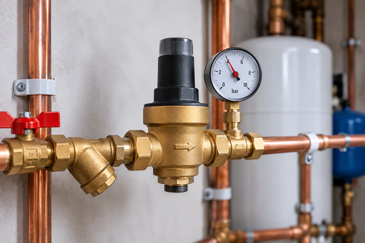
Pressure reducing valves play an important role in controlling water pressure within domestic plumbing systems. They are used where incoming pressure needs to be reduced to a controlled downstream pressure, helping protect pipework, appliances, valves and other components while maintaining suitable performance at outlets.
For trainee plumbers, pressure reducing valves provide an important connection between the theory of water pressure and the practical operation of a plumbing installation. A plumber needs to recognise the difference between static pressure, dynamic pressure and flow rate, while also understanding that high pressure is not necessarily an advantage.
Pressure reducing valves are particularly important in modern mains fed plumbing. They can be used to regulate supplies to sections of a property and form part of the inlet control arrangements serving many unvented hot water cylinders.
This article examines the construction and operation of pressure reducing valves, their relationship with flow and pressure, installation principles and the faults plumbers may encounter when working on domestic systems.
A Pressure Reducing Valve
A pressure reducing valve, commonly shortened to PRV, reduces a higher inlet pressure to a lower controlled outlet pressure.
Mains water pressure can vary considerably according to the supply network, property location, elevation and local demand. Pressure may also fluctuate during different periods of the day.
Allowing excessive pressure to act directly on every component within a property can contribute to problems such as:
- Increased stress on fittings
- Noisy pipework
- Increased water consumption
- Greater discharge from outlets
- Premature valve wear
- Increased risk of leakage
- Poor operation of pressure sensitive equipment
A correctly selected and installed PRV creates more predictable pressure conditions downstream.
Water Pressure in Domestic Plumbing
Before looking at the valve itself, it is important to recognise that water pressure is not a single fixed value throughout a plumbing installation.
Pressure can be influenced by:
- Incoming mains conditions
- Property height
- Pipe diameter
- Pipe length
- Fittings and restrictions
- Simultaneous demand
- Valve settings
The pressure measured while no water is moving can also be different from the pressure available while outlets are being used.
This distinction is fundamental when assessing whether a pressure reducing valve is operating correctly.
Static Pressure
Static pressure is measured while there is no water flowing through the system.
For example, a gauge connected to the incoming mains while every outlet is closed will indicate the static pressure at that point.
Static pressure can appear perfectly adequate even where a customer experiences poor performance at taps or showers.
For this reason, static pressure alone does not provide a complete picture of system performance.
Dynamic Pressure
Dynamic pressure is the pressure available while water is flowing.
Opening one or more outlets introduces resistance through the pipework, valves and fittings. The measured pressure may consequently fall.
The difference between static and dynamic conditions can provide useful diagnostic information.
A property may have relatively high static mains pressure but experience a substantial pressure drop as soon as several outlets are opened. This could indicate a supply limitation or restriction rather than a simple pressure setting problem.
Pressure and Flow Rate
Pressure and flow rate are related, but they are not the same thing.
Pressure represents the force available to move water through the system.
Flow rate represents the volume of water passing a particular point over a period of time, commonly expressed in litres per minute.
Poor flow at a tap does not automatically mean the incoming water pressure is low.
Reduced flow can result from:
- Undersized pipework
- Long pipe runs
- Partially closed valves
- Blocked strainers
- Scale
- Restricted fittings
- Excessive simultaneous demand
This distinction becomes particularly important when diagnosing complaints about showers and bath filling times.
High Mains Pressure
High incoming water pressure can place unnecessary stress on a domestic plumbing system.
Potential consequences include:
- Water hammer
- Increased outlet noise
- Greater wear on valves
- Excessive flow from taps
- Increased water consumption
- Leakage from vulnerable joints
- Problems with pressure sensitive appliances
Installing a suitable pressure reducing valve can help create controlled conditions downstream.
The objective is not simply to reduce pressure as much as possible. The valve needs to provide a pressure appropriate for the system and equipment it supplies.
Pressure Reducing Valve Construction
Although designs vary between manufacturers, a typical pressure reducing valve contains several key components.
These can include:
- Valve body
- Inlet connection
- Outlet connection
- Valve seat
- Spring
- Diaphragm
- Adjustment mechanism
- Strainer where incorporated
- Pressure gauge connection on some models
The interaction between the spring, diaphragm and valve seat allows the PRV to respond automatically to changes in downstream pressure.
Pressure Reducing Valve Diagram
A simplified section through a PRV can help trainees visualise its operation.
Adjustment
│
▼
┌───────────┐
│ Spring │
└─────┬─────┘
│
┌────┴────┐
│Diaphragm│
└────┬────┘
│
Incoming ▼ Controlled
Mains ─────► [ Valve Seat ] ─────► Outlet
Pressure Pressure
The precise internal construction varies, but the operating principle is based on balancing forces within the valve.
The Spring
The spring applies force to the valve mechanism.
Adjusting the spring tension changes the downstream pressure that the valve attempts to maintain.
Greater spring compression generally corresponds with a higher controlled outlet pressure, although adjustment procedures depend upon the individual valve.
Plumbers should always use manufacturer instructions rather than assuming all PRVs are adjusted in the same way.
The Diaphragm
The diaphragm responds to pressure on the downstream side of the valve.
As outlet pressure changes, the diaphragm moves and alters the position of the valve mechanism.
This allows the PRV to regulate water passing through it continually.
The valve therefore does not simply create a fixed restriction. It responds to downstream pressure conditions.
The Valve Seat
The valve seat controls the amount of water passing from the inlet to the outlet.
When downstream pressure falls, the valve can open further and allow more water through.
As downstream pressure reaches the intended level, the valve moves towards its regulating position.
Damage, scale or debris around the valve seat can affect regulation and may allow pressure to creep upwards when outlets are closed.
Basic Operating Sequence
The operating principle can be considered as a simple sequence:
1. High pressure water reaches the inlet.
2. Water passes through the regulating valve.
3. Downstream pressure acts against the diaphragm.
4. The diaphragm works against the spring.
5. The valve opening adjusts.
6. Outlet pressure is controlled.
7. The valve continues responding as demand changes.
This happens automatically during normal use.
Pressure Regulation Under Demand
A good PRV needs to maintain suitable downstream pressure across the expected range of flow rates.
When a tap opens, downstream pressure initially changes.
The valve responds by altering its opening to allow sufficient water through while continuing to regulate the outlet pressure.
As demand changes, the valve continually adjusts.
This is one reason correct valve sizing matters. A PRV that is unsuitable for the required flow can restrict performance even if its nominal pressure setting appears correct.
PRVs in Domestic Cold Water Systems
Pressure reducing valves may be installed to regulate the incoming supply to an entire property or a particular section of the plumbing system.
Possible applications include:
- High pressure mains supplies
- Multi storey properties
- Pressure sensitive appliances
- Hot water systems
- Individual branches
- Properties requiring balanced supplies
The location and pressure setting should reflect the intended system design.
PRVs and Unvented Hot Water Cylinders
Pressure control is particularly important with unvented hot water systems.
An unvented cylinder receives water directly from the mains and stores it under pressure. The incoming supply therefore needs to operate within the limits specified by the cylinder manufacturer.
The inlet control arrangement may incorporate several functions, including:
- Pressure reduction
- Backflow prevention
- Expansion relief
- Straining
These components may be supplied individually or combined within a manufacturer designed inlet control set.
The pressure reducing element ensures that the cylinder receives water at the intended operating pressure even where incoming mains pressure is considerably higher.
Combination Inlet Control Valves
Many unvented cylinders use a combination inlet control valve rather than a series of completely separate components.
Depending on the design, a combined unit may incorporate:
- Pressure reducing valve
- Check valve
- Strainer
- Expansion relief valve
Combining these functions simplifies installation while maintaining the pressure and safety controls required by the system.
Plumbers should identify the actual manufacturer arrangement rather than assuming every inlet control set contains the same components.
Balanced Cold Water Supplies
A mains pressure hot water system may require balanced cold supplies to certain outlets.
Consider a mixer shower supplied with hot water from an unvented cylinder operating at a controlled pressure.
If the cold supply reaches the mixer at substantially different pressure, performance can be affected.
A balanced cold connection can provide cold water at pressure conditions compatible with the hot water supply.
This can improve:
- Mixer operation
- Shower performance
- Temperature stability
- User comfort
The correct connection point depends upon the inlet control arrangement and manufacturer instructions.
Valve Orientation
Pressure reducing valves are designed with a specific direction of flow.
An arrow is commonly marked on the valve body to indicate the correct orientation.
Installing a valve backwards can prevent correct operation.
Other manufacturer requirements may relate to:
- Horizontal or vertical installation
- Gauge position
- Strainer access
- Adjustment access
- Servicing clearances
Installation should always follow the instructions supplied with the valve.
Strainers
Debris within the incoming water supply can affect the internal components of a PRV.
A strainer helps protect the valve seat and regulating mechanism from particles that could interfere with operation.
Strainers may collect:
- Installation debris
- Pipe fragments
- Scale particles
- Sediment
A partially blocked strainer can create a restriction that reduces flow downstream.
This provides another example of the difference between pressure and flow. A customer may describe the problem as low pressure when the actual fault is restricted flow through a contaminated strainer.
Pressure Gauges
Pressure gauges are extremely useful when commissioning and diagnosing PRVs
Measurements may be taken:
- Upstream of the valve
- Downstream of the valve
- Under static conditions
- Under flowing conditions
Comparing these readings allows an engineer to assess the behaviour of the valve.
For example, high upstream pressure combined with unexpectedly low downstream pressure under demand may indicate a restriction or an incorrectly adjusted valve.
Measuring Before Adjustment
A common diagnostic mistake is adjusting a PRV before establishing the existing pressure conditions.
Doing so removes useful evidence.
A better approach is to record:
1. Upstream static pressure.
2. Downstream static pressure.
3. Downstream pressure under demand.
4. Flow rate where appropriate.
5. Existing valve setting where identifiable.
Only after these conditions are understood should adjustment or further investigation take place.
Selecting a Pressure Reducing Valve
PRVs are available in different sizes, pressure ranges and flow capacities.
Selection should consider:
- Maximum inlet pressure
- Required outlet pressure
- Required flow rate
- Pipe size
- Water temperature
- Intended application
- Manufacturer requirements
- Potable water suitability
A valve should not be selected solely because its threaded connections match the existing pipework.
The operating characteristics need to suit the installation.
Pipe Size and Flow Capacity
Pipe size influences the amount of water that can be delivered without excessive pressure loss.
Installing a suitable PRV within an inadequately sized pipe does not correct the limitations of the pipework.
Likewise, installing an oversized valve does not necessarily improve system performance.
The complete installation needs to be considered, including:
- Incoming supply
- Pipe diameter
- Pipe length
- Fittings
- Elevation
- Simultaneous demand
- Required outlet flow
This system approach is essential when diagnosing poor performance.
Pressure Loss Across Components
Every component within a flowing plumbing system introduces some resistance.
This can include:
- Stop valves
- Check valves
- Strainers
- PRVs
- Water meters
- Filters
- Fittings
- Pipework
Individually, these pressure losses may be relatively small. Together, they can significantly affect available pressure under high demand.
Plumbers therefore need to consider the complete water path rather than assessing one component in isolation.
Pressure Creep
Pressure creep occurs when downstream pressure gradually increases above the intended setting while there is little or no demand.
Possible causes include contamination or damage preventing the valve seat from closing correctly.
Symptoms can include:
- Downstream pressure rising while outlets are closed
- Safety devices operating further downstream
- Pressure sensitive equipment experiencing excessive pressure
- Intermittent leakage
Testing static pressure over a suitable period can help identify this behaviour.
Pressure creep should not be confused with normal short-term pressure changes elsewhere in the system.
Low Downstream Pressure
A customer may complain that water pressure became poor after a PRV was installed or serviced.
Possible causes include:
- Incorrect valve setting
- Blocked strainer
- Undersized valve
- Low incoming pressure
- Excessive flow demand
- Restricted pipework
- Partially closed isolation valve
The engineer should measure conditions before deciding that the PRV itself is defective.
Noisy Pressure Reducing Valves
Noise from a PRV can sometimes indicate unsuitable operating conditions.
Possible causes include:
- Excessive flow velocity
- Incorrect valve sizing
- Debris
- Internal wear
- Unstable pressure conditions
- Cavitation in unsuitable conditions
Noise should be investigated rather than automatically accepted as normal valve operation.
PRVs and Water Hammer
High water velocity and rapidly closing outlets can contribute to water hammer.
Reducing excessive supply pressure may help reduce the forces involved, but a PRV should not automatically be regarded as the complete solution to every water hammer problem.
The plumber should consider:
- Water velocity
- Pipe support
- Quick closing valves
- Appliance solenoid valves
- Pipework layout
- Pressure conditions
Effective diagnosis requires identifying the mechanism creating the shock wave.
PRVs and Expansion
Pressure reduction and expansion control are related but separate functions.
A pressure reducing valve controls the pressure supplied downstream.
An expansion vessel accommodates increased water volume caused by thermal expansion.
Where a check valve or inlet control arrangement prevents expanded water from returning towards the mains, suitable expansion provision becomes particularly important.
Trainee plumbers should therefore avoid thinking of a PRV as a component that independently controls every pressure condition within a hot water system.
Backflow Prevention
Check valves are frequently installed alongside pressure reducing equipment, particularly within inlet control assemblies.
Their purpose is different.
A PRV regulates pressure.
A check valve prevents reverse flow.
Backflow prevention is an important part of protecting wholesome water supplies and is covered in greater detail within Water Regulations training.
Understanding these individual functions makes complex valve assemblies much easier to interpret.
Installation Debris
New installations can contain debris left from pipe cutting, jointing and construction work.
If debris reaches a pressure reducing valve, it may become trapped around the strainer or valve seat.
This can result in:
- Reduced flow
- Poor regulation
- Pressure creep
- Noise
- Complete valve malfunction
Correct flushing and commissioning therefore contribute directly to reliable PRV operation.
Commissioning a PRV
Commissioning should follow manufacturer instructions and the requirements of the wider installation.
A typical process may involve:
- Confirming correct valve orientation
- Opening the water supply carefully
- Checking for leaks
- Measuring upstream pressure
- Measuring downstream pressure
- Setting the required outlet pressure where adjustable
- Checking pressure under demand
- Confirming suitable flow
- Inspecting associated components
The final setting should suit the equipment and plumbing system supplied by the valve.
Fault Diagnosis
Pressure reducing valves provide a useful example of the importance of diagnosing plumbing systems rather than simply replacing individual components.
If a customer reports poor shower performance, the PRV may be responsible, but so could the incoming supply, pipe sizing, strainer, isolation valves or simultaneous water demand.
Likewise, excessive downstream pressure could indicate an incorrect setting, damaged valve seat or pressure creep.
The plumber therefore needs measurements and observations before concluding.
Understanding static pressure, dynamic pressure, flow rate and pressure loss allows the engineer to interpret these symptoms much more accurately.
Diagnosing Pressure Reducing Valve Faults
Pressure reducing valve faults are not always immediately obvious. A customer may report poor flow, fluctuating shower performance, noisy pipework or excessive pressure without realising that pressure regulation is involved.
Equally, the presence of a PRV does not mean every pressure-related problem originates at the valve. Effective diagnosis requires the plumber to assess the incoming supply, downstream pressure, flow rate, pipework restrictions and equipment supplied by the valve.
Establishing The Customer Complaint
Fault diagnosis should begin with the symptoms experienced by the customer.
Useful questions include:
- Has the problem developed recently?
- Does it affect hot and cold water?
- Does it affect every outlet?
- Is the problem worse at particular times?
- Does performance change when several outlets operate?
- Has any plumbing work recently been completed?
- Is there noise from the pipework?
- Have any safety valves started discharging?
These observations can help determine whether the problem involves the incoming supply, pressure regulation or something further downstream.
Upstream and Downstream Measurements
Before condemning a PRV, the engineer should establish the pressure available upstream and compare it with conditions downstream.
Testing should consider both static and flowing conditions because a mains supply may show adequate pressure while no water is being used but fall substantially under demand.
Measurements may reveal:
- High inlet pressure and correct outlet pressure
- High inlet pressure and excessive outlet pressure
- High inlet pressure and unusually low outlet pressure
- Low inlet pressure and low outlet pressure
- Stable static pressure but poor pressure under flow
Pressure measurements should be recorded before changing the valve setting.
Static and Dynamic Testing
Static testing is carried out while downstream outlets are closed. This allows the engineer to compare incoming pressure with the controlled outlet pressure.
Dynamic testing measures conditions while water is flowing.
Opening an outlet introduces demand and allows the engineer to observe how the PRV and supply respond. Additional outlets can then be opened where appropriate to assess the effect of increased demand.
A significant pressure reduction under flow could result from:
- Restricted PRV
- Blocked strainer
- Undersized valve
- Restricted pipework
- Partially closed isolation valve
- Inadequate incoming supply
- Excessive simultaneous demand
Flow rate measurements can provide additional evidence, particularly where the customer describes the problem as poor pressure despite satisfactory static readings.
Blocked Strainers
A contaminated strainer is worth checking where downstream performance has deteriorated.
Material trapped within a strainer may include:
- Scale
- Sediment
- Jointing debris
- Metal fragments
- Plastic swarf
- Corrosion products
As contamination increases, available flow through the valve can decrease.
A restricted strainer can produce a characteristic pattern. With every outlet closed, downstream pressure may gradually reach the expected static pressure. Once a high-flow outlet opens, pressure falls significantly because water cannot pass through the restriction quickly enough.
Incorrect Valve Adjustment
Some PRVs allow downstream pressure to be adjusted.
Incorrect adjustment may result in pressure that is either too high or too low for the installation.
Before altering the setting, the plumber should establish:
- Required downstream pressure
- Manufacturer specification
- Current static pressure
- Pressure under flow
- Equipment supplied downstream
Once adjustment is complete, the system should be tested again under normal operating conditions.
Pressure Creep
Pressure creep occurs when downstream pressure gradually increases above the intended regulated pressure while outlets are closed.
The valve may initially reduce pressure correctly, but the downstream reading slowly rises.
Possible causes include:
- Debris on the valve seat
- Scale deposits
- Damaged seat
- Internal wear
- Contaminated sealing surfaces
Because the increase may occur gradually, an immediate gauge reading after closing an outlet might not reveal the problem.
Pressure Creep and Unvented Cylinders
Pressure creep becomes particularly significant where a PRV supplies an unvented hot water cylinder.
If downstream pressure rises above the intended inlet control pressure, other components may begin responding to the abnormal condition.
The engineer might encounter:
- Expansion relief valve discharge
- Water visible through the tundish
- Changes in expansion vessel behaviour
- Higher pressure at hot water outlets
The visible symptom can therefore appear some distance downstream from the pressure-reducing component.
Valve Seat and Diaphragm Problems
The valve seat controls the passage of water through the PRV. Damage or contamination can prevent it from sealing correctly and may cause pressure creep, unstable outlet pressure or poor regulation.
The diaphragm responds to downstream pressure and controls the regulating mechanism. Damage or deterioration can affect the valve’s response to changing demand.
Possible symptoms include:
- Erratic downstream pressure
- Poor response to demand
- Incorrect pressure regulation
- Unstable operation
These symptoms can have several causes, so internal component failure should be supported by suitable testing before replacement is considered.
Pressure Too High Downstream
Excessive downstream pressure may result from:
- Incorrect adjustment
- Pressure creep
- Damaged valve seat
- Debris preventing closure
- Internal valve failure
- Incorrect valve specification
The engineer should determine whether the excessive pressure is continuously present or develops gradually after outlets close. This distinction can help separate an incorrect setting from pressure creep.
Pressure Too Low Downstream
Low downstream pressure can result from:
- Valve setting too low
- Blocked strainer
- Restricted valve
- Undersized PRV
- Partially closed isolation valve
- Low upstream pressure
- High simultaneous demand
- Restricted downstream pipework
Increasing the valve setting should not be the automatic response. If the actual problem is restricted flow or inadequate incoming supply, doing so may create excessive static pressure.
Fluctuating Outlet Pressure
Customers may report that shower or tap performance changes as other outlets are used.
Some pressure variation during changing demand is expected, but significant fluctuations can indicate:
- PRV response problems
- Insufficient incoming flow
- Incorrect valve sizing
- Restricted strainers
- Pipework limitations
- Unbalanced hot and cold supplies
The complete water path should be assessed rather than focusing solely on the outlet where the symptom appears.
Balanced Supplies and Mixer Performance
Pressure balance is particularly important at mixer outlets.
If hot water is supplied through a pressure-controlled unvented system while cold water reaches the mixer at substantially different pressure, temperature and flow, stability can be affected.
Correctly designed balanced supplies can support:
- Mixer operation
- Shower performance
- Temperature stability
- User comfort
The manufacturer’s instructions for the hot water system and outlet should determine the appropriate arrangement.
PRVs and Thermostatic Mixing Valves
Pressure reducing valves and thermostatic mixing valves perform different functions.
A PRV controls water pressure.
A thermostatic mixing valve controls mixed water temperature by blending hot and cold supplies.
Stable inlet conditions can support good mixer performance, but a PRV should never be regarded as a temperature control device.
PRVs and Expansion Vessels
Pressure reducing valves also interact indirectly with expansion arrangements.
Where a check valve prevents water from returning upstream, heated water needs somewhere to expand. An expansion vessel may provide this capacity within an unvented hot water system.
The two components perform different functions:
- The PRV controls incoming pressure.
- The expansion vessel accommodates increased water volume as temperature rises.
If expansion cannot be accommodated correctly, downstream pressure can increase even though the PRV itself is operating normally.
An engineer investigating excessive pressure around stored hot water therefore needs to distinguish between incoming pressure, pressure creep and thermal expansion.
Safety Valve Discharge
Where a customer reports water discharging from a safety valve or through a tundish, the PRV should form part of the investigation without automatically being treated as the cause.
Potential causes include:
- Excessive inlet pressure
- Pressure creep
- Expansion vessel problems
- Failed internal expansion provision
- Relief valve problems
- Temperature control faults
The operating conditions leading to the discharge need to be established before components are replaced.
Noise and Cavitation
A noisy PRV may produce humming, whistling or vibration as water flows.
Possible causes include:
- Excessive velocity
- Unsuitable valve sizing
- High pressure differential
- Debris
- Internal wear
- Unstable operating conditions
- Cavitation
Cavitation can occur where local pressure within a valve falls sufficiently for vapour bubbles to form and then collapse as pressure recovers. Repeated cavitation can contribute to noise, vibration, internal erosion and premature valve damage.
Correct valve selection therefore involves more than matching pipe diameter and required outlet pressure.
Water Hammer
Water hammer occurs when flowing water changes velocity rapidly, creating a pressure wave within the pipework.
High system pressure can increase the forces involved, so pressure regulation may form part of the solution where incoming pressure is excessive.
The plumber should also consider:
- Pipe support
- Water velocity
- Quick closing valves
- Appliance solenoid valves
- Pipe sizing
- Pipework layout
A PRV should not automatically be treated as the complete solution to every water hammer problem.
Isolation Valves
A partially closed isolation valve upstream of the PRV can create a significant flow restriction.
Static downstream pressure may still appear acceptable because pressure can gradually equalise while no water is being used. Once an outlet opens, the restriction becomes apparent, and downstream pressure falls.
Checking that service valves are correctly positioned is therefore a simple but important part of inspection.
Recent Plumbing Work
Where a pressure problem appears immediately after plumbing work, the engineer should consider whether the work has altered the system.
Potential causes include:
- Isolation valve not fully reopened
- Debris introduced into a strainer
- PRV setting altered
- Valve installed backwards
- Pipework changed
- New equipment increasing demand
- Balanced supply arrangement altered
Most PRVs have a clearly marked direction of flow. A valve installed backwards may fail to regulate correctly or significantly restrict the water supply.
Incorrect Valve Sizing
A PRV can have the correct connection size and still be unsuitable for the application.
An undersized valve may create excessive pressure loss at higher flow rates, while an incorrectly selected valve may operate outside its intended control range.
Selection should take into account:
- Maximum flow requirement
- Inlet pressure
- Required outlet pressure
- Permitted pressure differential
- Valve flow characteristics
- Manufacturer data
This becomes increasingly important in larger homes where several outlets may operate simultaneously.
Pressure Reducing Valve Fault Finding
A single structured process can bring these checks together.
Customer Reports Pressure Problem
│
▼
Check Incoming Supply
│
▼
Measure Upstream Static Pressure
│
▼
Measure Downstream Static Pressure
│
▼
Open An Outlet
│
▼
Check Dynamic Pressure And Flow
│
▼
Significant Pressure Drop?
┌─────┴─────┐
Yes No
│ │
Check Restrictions Observe Static
And Available Flow Downstream Pressure
│ │
│ Pressure Creeps Up?
│ ┌──┴──┐
│ Yes No
│ │ │
│ Inspect Investigate
│ PRV Seat Other Causes
│
▼
Check Strainer, Valves,
Pipework And PRV Capacity
│
▼
Repair Or Adjust
│
▼
Recommission
This provides the main diagnostic framework for the article without needing several separate fault scenarios covering the same sequence.
Fault Symptoms and Possible Causes
| Symptom | Possible Cause |
|---|---|
| High downstream pressure | Incorrect setting, pressure creep or internal PRV fault |
| Low downstream static pressure | Incorrect setting, low inlet pressure or valve fault |
| Good static pressure but poor flow | Blocked strainer, restriction, inadequate supply or undersized valve |
| Downstream pressure gradually rises | Valve seat contamination, wear or pressure creep |
| Noise during high flow | Excessive velocity, sizing issue, pressure differential or cavitation |
| Pressure changes as other outlets open | Supply limitation, pipework restriction or valve capacity |
| Unvented cylinder safety valve discharge | Inlet pressure, pressure creep, expansion or another safety system fault |
| Poor mixer shower performance | Pressure imbalance, flow limitation or outlet fault |
These observations should be treated as diagnostic clues rather than confirmation of a particular component failure.
Inspection and Maintenance
Pressure reducing valves should remain accessible for inspection and servicing where required.
Routine checks can include:
- External condition
- Signs of leakage
- Correct flow direction
- Upstream pressure
- Downstream pressure
- Performance under demand
- Strainer condition
- Adjustment security
- Associated isolation valves
Maintenance requirements vary between manufacturers, so the relevant instructions should always be consulted.
Replacement Considerations
Where a PRV requires replacement, the new valve should be selected according to system requirements rather than appearance alone.
The engineer should confirm:
- Connection size
- Maximum inlet pressure
- Adjustable or fixed outlet range
- Flow capacity
- Temperature rating
- Potable water suitability
- Installation orientation
- Manufacturer requirements
Where the PRV forms part of an unvented cylinder inlet control set, replacement components should be suitable for that specific system.
Commissioning After Repair
Any repair, adjustment or replacement should be followed by appropriate recommissioning.
Checks should include:
1. Confirming isolation valves are correctly positioned.
2. Checking for leakage.
3. Measuring upstream static pressure.
4. Measuring downstream static pressure.
5. Testing pressure under demand.
6. Checking available flow.
7. Confirming downstream equipment operates correctly.
8. Recording settings where appropriate.
For unvented hot water systems, work should be undertaken within the engineer’s competence and the complete installation left operating in accordance with manufacturer requirements.
PRVs As Part Of The Complete System
A pressure reducing valve should be considered as one component within a complete plumbing installation. Its position and setting need to suit the equipment downstream while allowing the system to operate correctly during normal domestic use.
A typical arrangement might include:
Incoming Mains
│
▼
Internal Stop Valve
│
▼
Strainer
│
▼
Pressure Reducing Valve
│
▼
Controlled Cold Supply
│
├────────► Cold Water Outlets
│
└────────► Hot Water System
The actual arrangement will depend on the property and equipment installed. Some systems regulate a large section of the property, while others use pressure control specifically for an appliance or stored hot water system.
Whole Property Pressure Reduction
Where incoming mains pressure is particularly high, a PRV may be used to regulate the supply serving much of the property.
This can provide more controlled operating conditions for taps, showers, WC filling valves, appliances and water heating equipment.
The chosen pressure still needs to provide satisfactory service throughout the building. This is particularly relevant in taller properties because elevation affects the pressure available at upper floors.
A townhouse with a plant area at lower ground level and bathrooms several floors above presents different design considerations from a bungalow, even if the incoming mains conditions are similar.
Local Pressure Regulation
Pressure reduction can also be applied to a particular part of an installation rather than the whole property.
This is particularly relevant where equipment has defined inlet requirements or where a hot water system operates at a controlled pressure.
The relationship between regulated and unregulated supplies needs careful consideration where they later meet at mixer outlets.
Water Efficiency
Controlling unnecessarily high pressure can contribute to more efficient water use.
High pressure can result in greater discharge from outlets than the user requires. Appropriate pressure control can reduce this effect while still maintaining satisfactory performance.
Pressure regulation forms only one part of efficient plumbing design. Suitable fittings, sensible distribution design and appropriate flow control also contribute to overall consumption.
Water Regulations and Pressure Control
Pressure reducing valves installed on wholesome water supplies need to be suitable for their intended application and installed as part of a compliant water system.
The wider installation can involve requirements relating to:
- Suitable materials and fittings
- Backflow prevention
- Accessibility
- Isolation
- Prevention of contamination
- Water efficiency
- Correct installation practice
This becomes particularly important where several functions are combined within a single valve assembly.
Backflow Prevention
A pressure reducing valve should not be confused with a backflow prevention device.
A PRV regulates pressure. A suitable check valve or other backflow prevention arrangement is used to prevent reverse flow where required.
Some combination inlet control valves incorporate both functions within the same assembly. Being able to identify the purpose of each section is therefore important for installation, servicing and fault diagnosis.
Fluid Categories
Backflow protection is determined by the potential contamination risk associated with the water downstream.
The Water Supply (Water Fittings) Regulations classify fluids according to the level of health risk they present. The appropriate form of backflow protection depends on this classification and the particular installation.
A PRV may sit close to backflow prevention equipment, but pressure reduction should not be treated as backflow protection.
Fluid categories and the different methods of protecting wholesome water supplies will be covered separately within this plumbing series.
PRVs and Unvented Hot Water Safety
Pressure regulation has an important function within unvented hot water systems.
An unvented cylinder stores domestic water under pressure and uses a coordinated arrangement of controls and safety devices. Depending on the manufacturer’s design, these can include:
- Pressure reducing valve
- Check valve
- Strainer
- Expansion relief valve
- Expansion vessel or internal expansion arrangement
- Temperature and pressure relief valve
- Thermostat
- Thermal cut out
The pressure reducing element establishes the appropriate inlet conditions. Other components protect against reverse flow, thermal expansion, excessive pressure and excessive temperature.
These individual functions should remain distinct in the engineer’s mind, even where several devices are incorporated into a single inlet control assembly.
Approved Document G
Unvented hot water installations in England are subject to requirements within Approved Document G of the Building Regulations.
These requirements include provisions for the safe storage of hot water and protection against excessive temperature and pressure, together with suitable arrangements for discharging water from safety devices.
A PRV forms part of the control arrangement but is not the primary answer to every safety condition that can develop within an unvented cylinder.
Engineers working on these systems should follow the cylinder manufacturer’s instructions and work within the scope of their competence.
Thermal Expansion After the Inlet Controls
Water expands as it is heated. Where the inlet arrangement prevents expanded water from returning towards the mains, suitable expansion provision is required.
An expansion vessel or manufacturer designed internal expansion arrangement provides space for this additional volume.
This creates a useful distinction for trainees:
- Pressure reduction establishes the incoming operating pressure.
- Expansion provision accommodates the increased volume of heated water.
- Relief devices protect the system if specified limits are exceeded.
Treating these as separate functions makes the complete inlet and safety arrangement much easier to interpret.
Balanced Hot and Cold Supplies
Mixer outlets generally perform best where the hot and cold supplies are suitable for the fitting and compatible with the system design.
With an unvented cylinder, the hot supply originates from water that has passed through the inlet control arrangement. Some systems therefore provide a designated balanced cold connection that can supply appropriate cold outlets under compatible conditions.
This may be relevant to:
- Mixer showers
- Thermostatic showers
- Basin mixers
- Bath mixers
The connection arrangement should follow the instructions supplied with the cylinder and outlet.
Replacing an Inlet Control Valve
Replacing a PRV within an unvented cylinder installation requires more than matching the connection size.
The existing assembly may combine:
- Pressure regulation
- Backflow prevention
- Expansion relief
- Straining
- Balanced cold supply
A replacement with different operating characteristics could alter the behaviour of the entire system.
Where the manufacturer specifies a particular inlet control assembly or replacement component, those requirements should be followed.
Accessibility for Servicing
PRVs and associated inlet controls should remain accessible.
An engineer may need access to:
- Measure pressure
- Inspect or clean a strainer
- Check the adjustment
- Investigate leakage
- Service permitted components
- Replace the valve
Placing pressure control equipment behind permanent finishes or within inaccessible voids can make future servicing unnecessarily difficult.
Good installation practice considers future maintenance from the outset.
Commissioning a New Installation
Commissioning confirms that the installed valve and the system it serves are operating as intended.
A suitable procedure may include:
1. Confirm the correct valve or inlet control assembly has been installed.
2. Check the direction of flow.
3. Inspect the associated pipework and fittings.
4. Confirm isolation valves are correctly positioned.
5. Flush the installation where required.
6. Introduce the water supply carefully.
7. Check all joints for leakage.
8. Record the incoming static pressure.
9. Record the regulated pressure.
10. Test operation under representative demand.
11. Confirm satisfactory performance at downstream outlets.
12. Check associated equipment in accordance with manufacturer instructions.
Where the PRV forms part of an unvented cylinder inlet control set, the complete cylinder commissioning procedure should also be followed.
Commissioning Records
Recording key measurements provides a useful reference for future servicing.
Information may include:
- Incoming static pressure
- Regulated pressure
- Pressure under representative demand
- Flow rate where relevant
- Adjustable PRV setting
- Date of commissioning
These records allow future engineers to compare current operating conditions with those present when the system was commissioned.
Alterations To Existing Systems
Changes to a domestic plumbing installation can alter the demands placed on existing pressure control equipment.
Examples include:
- Adding a bathroom
- Installing an unvented cylinder
- Converting from gravity-fed to mains-fed hot water
- Adding high flow showers
- Changing the incoming supply
- Extending a property
- Installing additional appliances
Existing components should therefore be reassessed where substantial alterations are made.
A PRV installed for the original system should not automatically be assumed suitable for a significantly different installation.
Upgrading Older Plumbing Systems
Converting an older property from traditional stored cold water and gravity-fed hot water to a mains-fed arrangement can expose existing components to very different operating conditions.
Pipework, taps, valves and fittings that previously worked at relatively low pressure may become subject to considerably higher pressure after conversion.
The condition and suitability of existing plumbing should therefore be assessed as part of the upgrade.
Pressure regulation may form part of the new design, but it does not remove the need to check whether the rest of the installation is appropriate for the changed operating conditions.
Working Within Competence
Pressure reducing valves can appear in relatively straightforward cold water installations as well as safety critical unvented hot water systems.
The engineer’s work should reflect their training and competence.
Recognising a PRV and knowing its operating principle does not automatically qualify someone to alter every system in which one appears.
This distinction is particularly important where work affects the inlet controls or safety devices associated with an unvented cylinder.
Water Regulations Training
Plumbers working on domestic water supplies need a strong knowledge of the Water Supply (Water Fittings) Regulations and the principles used to protect wholesome water.
Staffordshire Training Services offers the Water Regulations Certificate for plumbers and learners developing their professional plumbing knowledge.
The course covers areas relevant to domestic water installations, including water fittings requirements, contamination prevention, backflow protection and correct installation practice.
For engineers working with PRVs, this wider regulatory knowledge provides important context because pressure control equipment forms part of a water installation that also needs to protect water quality.
Hot Water Systems and Safety Training
Pressure reducing valves are also a key component within many unvented hot water installations.
Qualified plumbers and heating engineers progressing into this area can undertake the Hot Water Systems and Safety Course at Staffordshire Training Services.
Training in hot water safety develops the knowledge required to work with systems where pressure regulation operates alongside expansion control, relief valves, temperature controls and discharge arrangements.
Plumbing Training at Staffordshire Training Services
Pressure reducing valves demonstrate the progression from learning about individual plumbing components to interpreting complete domestic water systems.
Plumbing training combines technical principles with practical skills so candidates can develop the confidence to apply their knowledge to real installations at Staffordshire Training Services.
For engineers developing their careers, knowledge of pressure control connects directly with water regulations, hot water safety, backflow prevention, system commissioning and fault diagnosis. Building these subjects together creates a stronger foundation for working safely and competently across modern domestic plumbing systems.
Related Articles
- Understanding Water Pressure In Plumbing Systems
- Direct and Indirect Water Supply Systems
- Vented Hot Water Systems In Domestic Plumbing
- Unvented Hot Water Cylinders In Domestic Plumbing
- Expansion Vessels In Domestic Plumbing and Heating Systems
Prefer an AI Summary?