Modern boilers rely on electrical and electronic controls at almost every stage of operation. A boiler may have a satisfactory gas supply and sound combustion components yet still fail to operate because it has not received an electrical input, a safety condition has not been proved, or the control system cannot operate the required component.
For gas engineers, effective boiler fault finding therefore extends beyond checking gas pressure and combustion. Engineers need to follow an appliance operating sequence, interpret wiring diagrams, use electrical test equipment correctly, and determine whether a fault lies with the electrical supply, control circuit, sensor, actuator, or another part of the appliance.
Boilers contain numerous electrically operated components, including:
- printed circuit boards
- fans
- pumps
- gas valves
- ignition systems
- flame sensing circuits
- thermistors
- flow sensors
- pressure sensors
- thermostats
- diverter valve actuators
These components do not operate independently. The boiler control system monitors inputs and determines whether the conditions required to progress through the operating sequence are met.
Effective diagnosis therefore depends on identifying where the sequence stops and why it cannot continue.
Electrical Safety Before Boiler Fault Finding
Electrical testing introduces hazards that must be controlled before removing appliance covers or taking measurements.
Gas engineers carrying out electrical work must be competent for the tasks they undertake and should follow the appliance manufacturer’s instructions together with appropriate electrical safety procedures.
Where electrical isolation is required, switching an appliance off at its controls is not sufficient. The electrical supply must be safely isolated.
Safe Isolation
A safe isolation procedure should establish that the correct electrical circuit has been identified, isolated and proved dead before work begins.
The process typically involves:
1. Identifying the correct circuit and isolation point.
2. Switching off and isolating the supply.
3. Preventing inadvertent reconnection where appropriate.
4. Proving the voltage indicator on a suitable proving unit or known live source.
5. Testing between the relevant conductors to confirm the circuit is dead.
6. Reproving the voltage indicator after the test.
Proving the test instrument both before and after confirming dead provides evidence that the instrument remained functional throughout the procedure.
Staffordshire Training Services offers a dedicated Safe Isolation of Electrical Installations Course covering safe working practices for tradespeople working on or near electrical systems.
Live Electrical Testing
Some boiler diagnostic procedures require measurements while the appliance is energised.
Examples can include:
- checking supply voltage
- confirming a PCB output
- measuring voltage supplied to a fan or pump
- testing flame rectification current
- assessing control signals
Live testing introduces additional risk and should only be carried out where necessary, by a competent person using suitable equipment and an appropriate method of work.
Where the required diagnostic information can be obtained safely with the appliance isolated, there is no justification for unnecessary live testing.
Test Equipment
Electrical test instruments should be:
- suitable for the measurement
- in serviceable condition
- correctly rated
- used with appropriate leads and probes
- selected for the circuit being tested
Before taking a measurement, engineers should confirm both the function and range selected on the instrument.
A meter incorrectly configured for current measurement, for example, can create a very different situation from one configured for voltage measurement.
Boiler Electrical Supplies
Before investigating individual components, engineers should establish that the boiler is receiving the correct electrical supply.
Starting with the supply prevents wasting time diagnosing appliance components when the fault lies upstream.
Domestic boilers typically operate from a 230 V AC supply, although internal components and electronic circuits may operate at other voltages.
Line Conductor
The line conductor supplies the appliance with electrical power.
Loss of line voltage may result from:
- an open protective device
- a failed fused connection unit
- damaged wiring
- a loose terminal
- an external control fault
- loss of the property supply
If a boiler appears completely dead, confirming the electrical supply is one of the first diagnostic checks.
Neutral Conductor
A satisfactory line supply does not prove that the appliance has a complete circuit.
A disconnected or high resistance neutral may prevent the boiler from operating and can produce unusual electrical symptoms.
Engineers should therefore assess the complete supply rather than checking line voltage alone.
Protective Conductor
The protective conductor provides the earth connection required for electrical safety.
It can also be essential to appliance operation.
Flame rectification systems, for example, depend upon an effective earth path between the burner assembly and control system. Poor earth continuity can therefore cause flame detection faults even when the burner ignites successfully.
Polarity
Correct polarity is essential for many gas appliances.
A supply with reversed polarity may affect:
- appliance controls
- flame rectification
- safety systems
- electronic components
Therefore, verify polarity where required by the manufacturer’s commissioning and diagnostic procedures.
Permanent Live and Switched Live Supplies
Some boilers receive more than one line connection.
A permanent live supply may keep the appliance PCB energised continuously, while a switched live provides a demand signal from an external control.
This distinction is important during fault diagnosis.
A boiler may have a perfectly satisfactory permanent electrical supply but fail to operate because the switched demand signal is absent.
External controls may include:
- room thermostats
- programmers
- time controls
- smart heating controls
- zone controls
- wiring centres
If a boiler does not respond to a heating demand, the engineer should confirm it is receiving the required demand signal before investigating internal components.
Fuses and Protective Devices
Treat a blown fuse as evidence of a fault, not something to replace repeatedly.
Possible causes include:
- short circuits
- damaged wiring
- failed pumps
- fan faults
- component insulation failure
- moisture entering electrical components
- PCB defects
Where a replacement fuse operates again, further investigation is required.
Installing a higher rated fuse to prevent repeated operation is unsafe and can remove the protection intended by the appliance or circuit designer.
The Boiler Operating Sequence
One of the most effective ways to diagnose a modern boiler is to follow its operating sequence.
Instead of asking:
Which component has failed?
the engineer can ask:
At which stage has the boiler stopped progressing?
A typical fan assisted boiler sequence may follow this pattern:
Heat demand received
↓
PCB verifies starting conditions
↓
Pump and/or fan starts
↓
Required safety conditions are proved
↓
Ignition system energises
↓
Gas valve opens
↓
Burner ignites
↓
Flame supervision confirms flame
↓
Boiler enters normal operation
↓
Temperature and safety conditions remain monitored
The precise sequence varies between appliances. Always use the manufacturer’s instructions, wiring diagrams, and technical data when diagnosing a specific boiler.
Diagnosing the Point Of Failure
The stage at which operation stops provides valuable evidence.
For example, if there is no response to a heat demand, the engineer might investigate:
- electrical supply
- external controls
- demand signal
- PCB power supply
If the fan starts but ignition does not follow, the diagnostic direction changes towards:
- fan feedback
- airflow proving
- pressure switch arrangements where fitted
- ignition permissive conditions
- PCB inputs
If ignition occurs but the burner does not establish, investigation may move towards:
- gas supply
- gas valve operation
- ignition electrode
- gas pressure
If the burner establishes but immediately shuts down, flame supervision becomes a key area to investigate.
Following the sequence prevents replacing unrelated components simply because they appear on a fault code or are associated with the reported symptom.
Reading Boiler Wiring Diagrams
A wiring diagram maps the appliance’s electrical system.
Engineers who can follow this map can trace a signal from its source through switches, sensors and controls until it reaches the component being operated.
Manufacturer wiring diagrams show:
- mains supply
- PCB terminals
- external controls
- pumps
- fans
- gas valves
- thermostats
- thermistors
- sensors
- switches
- ignition components
- protective conductors
Symbols and layouts vary between manufacturers, so appliance specific documentation is essential.
Tracing A Circuit
Consider a simplified heating demand circuit.
A room thermostat closes and sends a heating demand to the boiler.
The engineer can trace:
Electrical supply
↓
Heating control
↓
Demand terminal
↓
PCB input
↓
PCB processing
↓
Required appliance output
If the demand reaches the PCB but the expected output is absent after all required safety conditions are satisfied, attention may shift to the control board or another condition preventing that output.
If the demand never reaches the PCB, replacing the PCB would not address the fault.
This simple distinction can save significant diagnostic time.
Inputs and Outputs
Viewing a boiler control system in terms of inputs and outputs provides a useful framework for electrical diagnosis.
The PCB receives information from the appliance and responds by controlling components.
Boiler Inputs
Depending on appliance design, inputs may include:
- room thermostat demand
- hot water demand
- thermistor resistance
- system pressure signal
- water flow detection
- fan feedback
- airflow proving
- flame signal
- high limit controls
These inputs tell the PCB the appliance’s current condition.
Boiler Outputs
Outputs may include:
- pump supply
- fan supply or control
- ignition
- gas valve operation
- diverter valve actuator
- display functions
The PCB will provide certain outputs only after it receives the required inputs.
This creates two distinct diagnostic questions.
Has the PCB received the inputs required to progress?
and
If the inputs are correct, has the PCB produced the required output?
That distinction is central to systematic electrical fault finding.
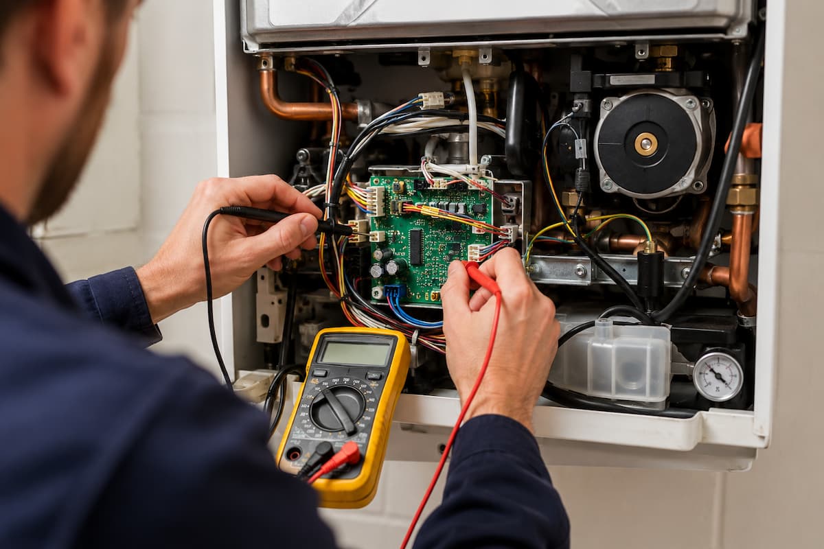
Using A Multimeter for Boiler Diagnostics
A multimeter lets engineers gather electrical evidence rather than relying solely on symptoms.
Depending on the appliance and diagnostic procedure, measurements may include:
- AC voltage
- DC voltage
- resistance
- continuity
- millivolts
- microamps
Each measurement answers a different question.
Voltage Testing
Voltage testing can establish whether electrical potential is present at a particular point in the circuit.
Suppose a boiler has received a heat demand, but the fan does not operate.
If the appliance operating sequence indicates the fan should be running, the engineer can determine whether the correct electrical supply or control signal is reaching it.
Voltage Present But Component Does Not Operate
Where the correct supply is present at a component, but it does not operate, investigation moves towards:
- component failure
- neutral integrity
- wiring connections
- appliance specific control requirements
Voltage alone does not automatically prove component failure.
Voltage Absent
Where the expected supply is absent, the engineer should work backwards through the control circuit.
Possible causes may include:
- PCB not commanding the component
- safety condition not satisfied
- open circuit
- wiring fault
- failed relay
- missing input
The next test should establish which of these possibilities applies.
Resistance Testing
Resistance measurements can be particularly useful when testing sensors and electrical components.
Normally, carry out resistance tests with the circuit safely isolated and according to the manufacturer’s procedures. You may need to disconnect components from the circuit to prevent parallel electrical paths from affecting the reading.
Thermistors provide one of the best examples of resistance based boiler diagnosis.
Thermistors and Temperature Sensors
Modern boilers use temperature sensors to provide continuous information to the PCB.
Many appliances use Negative Temperature Coefficient thermistors, usually called NTC thermistors.
An NTC thermistor changes resistance as its temperature changes.
As temperature rises, its resistance falls.
As temperature falls, its resistance rises.
The PCB interprets this resistance and uses it to determine the sensor temperature.
Thermistors may monitor:
- central heating flow temperature
- return temperature
- domestic hot water temperature
- stored water temperature
- other appliance specific temperatures
Diagnosing Thermistor Faults
Thermistors can fail in several ways.
Open Circuit Sensor
An open circuit prevents the PCB from receiving the expected resistance value.
Depending on appliance design, this may generate a fault code and prevent burner operation.
Short Circuit Sensor
A short circuit produces extremely low resistance and may be interpreted by the PCB as an implausibly high temperature.
The appliance may shut down in response.
Incorrect Resistance
A thermistor does not need to fail to cause problems.
A sensor whose resistance has drifted away from the correct value may cause:
- incorrect temperature control
- premature burner shutdown
- excessive cycling
- poor hot water performance
- inaccurate display temperatures
This is where resistance testing becomes particularly valuable.
Thermistor Resistance Example
An engineer investigating erratic boiler temperature control measures the thermistor resistance with the appliance safely isolated.
The engineer then compares the measured resistance with the manufacturer’s resistance and temperature data.
If the sensor is physically at approximately 40°C but its measured resistance corresponds to a significantly different temperature according to the manufacturer’s table, the sensor may be providing inaccurate information to the PCB.
This is stronger diagnostic evidence than replacing the thermistor solely because the boiler displays a temperature related fault code.
Illustrative Thermistor Behaviour
The following values demonstrate the relationship between temperature and resistance in an NTC thermistor. They are illustrative only and must not be used as manufacturer test values.
| Temperature | Illustrative Resistance Behaviour | Diagnostic Principle |
|---|---|---|
| Low temperature | Higher resistance | NTC resistance increases as temperature falls |
| Moderate temperature | Intermediate resistance | Compare measured value with manufacturer data |
| High temperature | Lower resistance | NTC resistance decreases as temperature rises |
| Open circuit | Extremely high or infinite resistance | Check sensor and wiring |
| Short circuit | Very low resistance | Check sensor and wiring |
Actual resistance values vary significantly between sensor designs. Engineers should always use the appliance manufacturer’s technical data when deciding whether a thermistor is operating within specification.
Continuity Testing
Continuity testing helps determine whether an electrical path exists through wiring or certain components.
Potential applications include checking:
- wiring conductors
- fuses
- switches
- thermostats
- certain safety controls
- connections
A continuity buzzer is useful for rapid checks, but it should not be treated as proof that a circuit will operate correctly under load.
A conductor may show continuity yet still contain:
- excessive resistance
- damaged strands
- poor terminals
- heat affected connections
Where symptoms suggest this type of fault, further measurements may be required.
Boiler PCB Fault Diagnosis
The printed circuit board acts as the control centre of a modern boiler. It receives information from sensors and external controls, processes those signals and provides outputs to components including the fan, pump, ignition system and gas valve.
Because so many components connect to the PCB, fault codes and operating symptoms can sometimes indicate board failure even when the real problem originates elsewhere.
Replacing a PCB should therefore follow diagnosis, not assumption.
PCB Inputs
Depending on appliance design, the PCB may receive information from:
- heating controls
- hot water demand sensors
- thermistors
- water pressure sensors
- flow sensors
- fan feedback
- air proving controls
- flame sensing circuits
- temperature limit devices
If one required input is missing, or outside its permitted range, the PCB may deliberately prevent the operating sequence from progressing.
This is correct safety operation, not a PCB failure.
PCB Outputs
Once the necessary conditions have been satisfied, the PCB may provide outputs to:
- circulation pump
- combustion fan
- ignition system
- gas valve
- diverter valve actuator
- displays and indicators
The engineer can use the appliance operating sequence and wiring diagram to establish which output should be present at a particular stage.
Proving A PCB Fault
Before condemning a PCB, the diagnostic process should establish that:
1. The appliance has the correct electrical supply.
2. Polarity and earth arrangements are satisfactory.
3. Required external demand signals are present.
4. Relevant sensors are providing acceptable inputs.
5. Safety conditions required for operation have been satisfied.
6. Wiring and connections are intact.
7. The PCB should be producing a particular output at that stage.
8. The expected output is absent.
Even then, check the diagnosis against manufacturer procedures and technical data.
This approach matters because replacing a PCB without correcting the underlying fault may cause the replacement board to show the same symptoms.
Visual PCB Inspection
With the appliance safely isolated, visual inspection may identify:
- signs of overheating
- damaged tracks
- discoloured components
- moisture contamination
- corroded connections
- loose plugs
- damaged terminals
Visible damage can provide valuable evidence, but you should still investigate the cause.
For example, moisture damage may originate from a leaking hydraulic component positioned above the PCB. Replacing the board without repairing the leak would leave the cause unresolved.
Fan Electrical Faults
The combustion fan plays a central role in many modern boilers. It provides the airflow needed for combustion and helps remove combustion products safely.
Depending on the boiler design, the fan may use a straightforward electrical supply or a more sophisticated electronic speed-control and feedback arrangement.
Fan Fails To Start
Where the operating sequence requires the fan to run but it remains stationary, engineers should establish whether the fan is receiving the required electrical command.
Possible areas for investigation include:
- supply voltage
- neutral connection
- fan wiring
- PCB output
- fan motor
- electronic fan controls
- mechanical obstruction
If the required supply or control signal reaches the fan but it fails to operate, the diagnostic direction moves towards the fan itself.
If the required output is absent, the engineer should establish whether the PCB has received all the inputs needed to command fan operation.
Fan Runs But Boiler Does Not Progress
A rotating fan does not necessarily prove that the control system has received confirmation of satisfactory fan operation.
Depending on appliance design, the PCB may require:
- air pressure switch operation
- fan speed feedback
- differential pressure confirmation
- another appliance specific proving signal
The engineer should identify the relevant proving arrangement from the manufacturer’s technical information.
Fan Speed Faults
Modulating boilers may vary fan speed according to burner demand.
Incorrect fan operation can affect:
- ignition
- gas and air ratio
- combustion
- maximum appliance output
- flame stability
Where fan speed is controlled electronically, diagnosis may require checking both the supply and the relevant control or feedback signals.
Pump Electrical Faults
Boiler pumps circulate water through the heat exchanger and heating system. A pump fault can cause symptoms that initially appear related to temperature sensors, overheat controls, or the PCB.
Therefore, consider electrical and hydraulic diagnosis together.
Pump Does Not Operate
Possible electrical causes include:
- no supply from the PCB
- loose wiring
- failed motor
- electronic pump failure
- damaged connections
Mechanical or hydraulic causes may include:
- seized pump
- obstruction
- air
- restricted circulation
An engineer should establish whether the pump is being commanded to operate before deciding whether the pump itself has failed.
Pump Supply Present
If the manufacturer’s operating sequence requires pump operation and the correct electrical supply is present, but the pump remains stationary, further investigation is justified.
The engineer should still consider whether the pump requires additional control signals rather than relying solely on the presence of mains voltage.
Pump Supply Absent
Where the expected supply is absent, possible causes include:
- missing PCB output
- unsatisfied control condition
- wiring fault
- failed PCB relay
Working backwards through the sequence helps identify the relevant cause.
Gas Valve Electrical Diagnosis
Modern automatic gas valves are controlled electrically by the appliance control system.
Energise the gas valve only after the required safety conditions are met, and the ignition sequence has reached the correct stage.
Electrical diagnosis of a gas valve therefore needs to consider both the valve and the controls that operate it.
No Gas At The Burner
If ignition is present but the burner does not establish, engineers may need to determine whether the gas valve is being commanded to open.
Checks can include:
- gas supply availability
- inlet gas pressure
- valve electrical connections
- PCB output
- appliance safety sequence
- manufacturer specified valve control signals
The absence of gas at the burner does not automatically indicate gas valve failure.
Electrical Command Present
Where the correct manufacturer-specified electrical command reaches the gas valve, but it does not respond, the valve becomes a stronger diagnostic suspect.
Measure resistance or take electrical measurements on valve coils only when the manufacturer provides an appropriate procedure and test data.
Electrical Command Absent
If the gas valve is not receiving the expected command, the engineer should investigate the earlier stages of the operating sequence.
The PCB may deliberately prevent gas release because another safety condition has not been met.
Modulating Gas Valves
Many condensing boilers use modulating gas valves as part of a closely controlled gas and air system.
Diagnosis can involve:
- valve control signal
- fan operation
- gas supply
- combustion readings
- manufacturer specified adjustment procedures
Never use unauthorised adjustment as a diagnostic shortcut.
Ignition Circuit Faults
The ignition system creates the spark required to establish combustion.
Depending on appliance design, the ignition transformer may be incorporated into the PCB or fitted as a separate component.
An ignition fault may present as:
- no spark
- weak spark
- intermittent spark
- spark in the wrong location
- repeated ignition attempts
No Ignition Spark
Where the appliance reaches the ignition stage but no spark is produced, possible causes include:
- failed ignition transformer
- PCB output fault
- damaged high tension lead
- damaged electrode
- incorrect electrode gap
- poor earth path
- insulation breakdown
Use the wiring diagram and manufacturer test procedures to guide the investigation.
Spark Position
A visible spark does not necessarily mean ignition conditions are satisfactory.
The spark needs to occur at the position intended by the manufacturer.
A damaged or incorrectly positioned electrode may allow the spark to track:
- to the burner casing
- across damaged insulation
- to an unintended earth point
This can prevent reliable burner ignition despite audible sparking.
Electrode Condition
Inspection should include:
- electrode position
- ceramic insulation
- electrode gap
- contamination
- HT lead condition
- electrical connections
Any adjustment should remain within manufacturer specifications.
Flame Rectification Circuit
Once ignition occurs, many modern boilers use flame rectification to confirm that a burner flame has been established.
The flame sensing circuit typically involves:
- ionisation electrode
- burner flame
- burner earth path
- connecting lead
- PCB flame detection circuit
If the PCB does not receive an adequate flame signal, it will close the gas valve even if the burner has visibly ignited.
Staffordshire Training Services covers detailed flame supervision principles in its article on Gas Safety Devices and Flame Supervision Systems For Gas Engineers.
From an electrical diagnostic perspective, engineers should consider:
- electrode condition
- electrode position
- wiring
- earth continuity
- polarity
- flame quality
- ionisation current
- PCB input
A flame detection fault should not automatically result in replacement of the sensing electrode.
Boiler Interlocks and Permissive Circuits
A boiler can have a satisfactory electrical supply and a valid demand for heat but still refuse to ignite.
This often occurs because the control system has not received permission to progress to the next stage.
Modern appliances monitor several operating and safety conditions before opening the gas valve.
These conditions are sometimes called interlocks or permissives.
Water Pressure
Many sealed system boilers monitor system water pressure electronically.
If the pressure falls outside the permitted operating range, the PCB may prevent the burner from operating.
Before diagnosing the pressure sensor, engineers should establish whether the hydraulic pressure itself is satisfactory.
Airflow Proving
Fan-assisted appliances may require confirmation of suitable airflow before ignition.
Depending on appliance design, this may involve:
- an air pressure switch
- fan speed feedback
- pressure sensing
- electronic fan communication
If the required condition is not met, the ignition sequence cannot progress.
Temperature Limits
High temperature controls protect the boiler against unsafe operating temperatures.
An activated limit device may prevent further burner operation until:
- the appliance cools
- the fault is rectified
- a manual reset is carried out where required
Repeated temperature-limit operation should prompt investigation of the cause rather than repeated resetting.
Hydraulic Flow
Some appliances monitor water movement before or during burner operation.
Insufficient circulation may arise from:
- pump failure
- closed valves
- blockage
- air
- restricted heat exchanger
- sensor problems
A hydraulic problem can therefore appear to be an electrical control fault because the PCB deliberately prevents or terminates burner operation.
Condensate Related Conditions
Condensing boilers depend on effective condensate removal.
Restrictions or appliance-specific condensate safety arrangements can interfere with operation.
If fault symptoms point to this area, engineers should inspect the condensate system per the manufacturer’s instructions rather than assuming an electronic component has failed.
Series Safety Circuits
Some appliances use several safety controls within a circuit that must remain complete before operation can proceed.
If any one device opens the circuit, the resulting symptom may be identical regardless of which control has operated.
For example, a circuit might include several temperature or safety devices. The PCB sees only that the required circuit is incomplete.
The engineer then needs to establish where continuity has been lost.
This is where a wiring diagram becomes particularly valuable.
Rather than replacing each component in turn, the engineer can trace the circuit and safely test individual sections.
Fault Codes as Diagnostic Evidence
Modern boilers provide fault codes designed to help engineers identify where an operating problem occurs.
Fault codes are valuable, but treat them as evidence rather than a component-replacement instruction.
A code usually indicates the condition the appliance detected. It does not always identify the root cause.
Primary Fault and Consequence
Consider a boiler reporting a flame failure code.
Possible causes might include:
- interrupted gas supply
- insufficient gas pressure
- ignition failure
- gas valve control problem
- flame sensing fault
- poor earth
- combustion instability
Replacing the flame electrode solely because the code relates to flame failure could therefore miss the actual cause.
Historic Fault Codes
Some boilers retain previous fault information.
Historic codes can help identify intermittent problems, but engineers need to distinguish between:
- the present fault
- previous unrelated faults
- secondary codes generated as a consequence of another problem
Use the appliance manufacturer’s diagnostic information to interpret the code history.
Multiple Fault Codes
Several codes appearing together may share a single underlying cause.
For example, an electrical supply problem could affect multiple sensors or components and generate several apparently unrelated errors.
Looking for relationships between codes can be more useful than investigating each one independently.
Electrical Fault Finding Decision Process
A structured sequence helps prevent unnecessary component replacement.
Boiler does not operate
↓
Correct electrical supply present?
↓
Polarity and protective conductor satisfactory?
↓
Protective devices and fuse satisfactory?
↓
Does the PCB receive power?
↓
Valid heating or hot water demand received?
↓
Required sensor and safety inputs satisfied?
↓
Does the PCB provide the expected output?
↓
Does the component receive the correct supply or control signal?
↓
Component operates?
↓
Next safety condition proved?
↓
Ignition sequence progresses?
↓
Burner establishes, and flame is confirmed?
↓
Appliance operates and modulates correctly?
At each stage, select the next measurement because it answers a specific diagnostic question.
Fault Scenario One: Boiler Completely Dead
A customer reports that the boiler display is blank and the appliance does not respond to either heating or hot water demand.
The engineer should resist immediately diagnosing PCB failure.
Initial Checks
The diagnostic sequence begins with:
- property electrical supply
- boiler isolation point
- fused connection unit
- boiler supply voltage
- line and neutral
- protective conductor
- appliance fuse where fitted
Suppose the engineer confirms that the correct supply reaches the boiler but the PCB receives no power beyond an internal protective fuse.
Further investigation finds that the fuse has operated.
Replacing it alone does not complete the diagnosis.
The engineer should determine why it operated.
If testing later identifies a failed component causing an electrical fault, address that component before returning the appliance to service.
The important diagnostic lesson is that a blank display is a symptom, not proof of PCB failure.
Fault Scenario Two: Heat Demand But Fan Does Not Start
The boiler display is operational, and a valid central heating demand reaches the appliance, but the fan remains stationary.
The engineer confirms from the manufacturer’s operating sequence that fan operation should be the next stage.
Diagnostic Direction
Checks may include:
1. Confirming the heat demand at the PCB.
2. Checking that relevant safety inputs are satisfied.
3. Establishing whether the PCB is providing the required fan output.
4. Checking wiring between the PCB and fan.
5. Assessing fan control and feedback arrangements.
If the correct command reaches the fan but it remains stationary, attention moves towards the fan assembly.
If no command is produced despite all required inputs being satisfied, investigation moves back to the control circuit and PCB.
The diagnostic decision is based on measurements rather than the reported symptom alone.
Fault Scenario Three: Fan Runs But Ignition Does Not Begin
The appliance receives a demand, and the fan starts, but there is no ignition spark and the gas valve does not open.
Because the fan has started, several earlier stages of the operating sequence have already been completed successfully.
The next question is whether the boiler has received confirmation that the conditions required for ignition are satisfactory.
Depending on appliance design, the engineer may investigate:
- fan feedback
- air proving
- pressure switch operation
- safety circuits
- temperature limits
- wiring
- PCB inputs
If the relevant proving signal is absent, the PCB may be correctly preventing ignition.
This distinction is essential. The lack of ignition does not necessarily indicate an ignition system fault.
The engineer should first establish whether the appliance has actually instructed the ignition system to operate.
Fault Scenario Four: Burner Lights Then Locks Out
A boiler that successfully reaches ignition but shuts down shortly afterwards has already completed several stages of its operating sequence.
The engineer knows that:
- an appliance demand has been recognised
- the control sequence has progressed
- the fan has operated where required
- ignition has taken place
- the gas valve has opened
- gas has reached the burner
The investigation can therefore concentrate on the stages immediately following ignition.
Diagnostic Direction
Depending on appliance design, checks may include:
1. Confirming that a stable flame is actually established.
2. Inspecting the flame sensing electrode and its position.
3. Checking the flame sensing lead.
4. Verifying polarity and earth continuity.
5. Measuring the flame signal where permitted by the manufacturer.
6. Checking gas pressure and burner operation.
7. Assessing combustion performance.
8. Confirming that the PCB is receiving the required flame signal.
If a healthy flame is present but the PCB does not receive an adequate flame signal, the problem may lie within the flame rectification circuit.
If the flame itself is unstable, however, the engineer needs to investigate the conditions producing that instability rather than treating the problem solely as an electrical fault.
Gas pressure, combustion air, burner condition and gas valve operation may all influence the result.
The Flame Electrode
A flame failure fault code can encourage engineers to concentrate immediately on the flame electrode.
The electrode is only one part of the circuit.
A flame rectification problem may originate from:
- poor earth continuity
- reversed polarity
- damaged sensing lead
- contaminated burner
- unstable combustion
- incorrect gas pressure
- damaged electrode
- PCB flame detection circuit
Testing each part of the circuit provides stronger evidence than replacing the electrode based solely on the displayed fault code.
Fault Scenario Five: Intermittent Boiler Operation
Intermittent faults can be particularly difficult because the appliance may operate normally while the engineer is present.
A customer might report that the boiler:
- occasionally fails to ignite
- resets without intervention
- loses heating after operating for a period
- displays different fault codes
- works correctly after cooling
- shuts down during higher demand
These symptoms require a different diagnostic approach from a permanent failure.
Reproducing The Fault
Where safe and practical, the engineer should attempt to reproduce the operating conditions associated with the fault.
Questions for the customer may establish whether the problem occurs:
- during heating demand
- during hot water demand
- after extended operation
- from a cold start
- during high appliance output
- after another control operates
This information can narrow the diagnostic area considerably.
Temperature Related Electrical Faults
Some electrical defects only become apparent as components warm.
Possible causes include:
- deteriorating PCB components
- heat affected terminals
- damaged solder joints
- failing motors
- sensor drift
- wiring affected by thermal movement
Measurements taken while the appliance is cold may therefore appear satisfactory.
Comparing readings before, during and after the fault occurs can provide valuable evidence.
Loose Connections
Vibration and repeated heating cycles can affect electrical connections.
Engineers should inspect connectors for:
- loose terminals
- damaged plugs
- discolouration
- corrosion
- signs of overheating
- damaged conductors
Simply pushing a loose connector back into position may temporarily remove the symptom without confirming whether the terminal itself is damaged.
Moisture Related Faults
Water or condensate entering electrical components can produce intermittent behaviour before complete failure occurs.
Inspection should consider:
- hydraulic leaks
- condensate leaks
- damaged seals
- corrosion around electrical connectors
- moisture marks near the PCB
If you identify moisture, repair its source rather than simply replacing the affected electrical component.
Electrical Faults Versus Gas and Hydraulic Faults
Boiler systems combine electrical, gas, combustion and hydraulic processes. A symptom associated with one system may originate in another.
Effective diagnosis therefore requires engineers to consider the appliance as a complete operating system.
Ignition Failure
An ignition failure could originate from an electrical problem such as:
- failed ignition transformer
- damaged electrode
- missing PCB output
- wiring fault
It could also originate from:
- interrupted gas supply
- inadequate gas pressure
- gas valve problem
- incorrect gas and air mixture
The fault code alone may not distinguish between these possibilities.
Boiler Overheating
An overheat condition may initially appear to indicate a faulty temperature sensor.
Possible causes also include:
- pump failure
- restricted circulation
- closed valves
- blocked heat exchanger
- air within the system
- genuine excessive temperature
The temperature control may actually be operating correctly by shutting the appliance down.
Poor Hot Water Performance
Poor domestic hot water performance can involve:
- thermistor faults
- flow sensor problems
- diverter valve operation
- restricted heat exchanger
- insufficient gas input
- control system faults
Electrical testing should therefore be combined with hydraulic and combustion checks where appropriate.
Repeated Flame Failure
A flame related lockout might originate from:
- flame sensing circuit
- earth continuity
- gas pressure
- burner condition
- gas valve
- combustion instability
A structured investigation identifies the responsible system before replacing components.
Boiler Electrical Fault Diagnosis Reference Table
| Symptom | Electrical Checks | Possible Causes | Diagnostic Direction |
|---|---|---|---|
| Boiler completely dead | Supply, polarity, fuse, PCB supply | Supply failure, fuse operation, wiring fault, PCB fault | Trace supply from isolation point to appliance controls |
| Heat demand but no response | Demand signal and PCB input | External control, wiring or PCB input fault | Confirm demand reaches the appliance |
| Fan does not start | Fan supply, control signal and wiring | Fan fault, missing PCB output, unsatisfied permissive | Establish whether the fan is being commanded to operate |
| Fan runs but no ignition | Proving circuits, safety inputs and ignition output | Air proving fault, safety circuit or ignition fault | Identify the next required stage in the operating sequence |
| Spark but no burner flame | Gas valve command and wiring | Gas valve, gas supply, pressure or ignition position | Combine electrical testing with gas supply checks |
| Burner lights then shuts down | Flame signal, polarity and earth continuity | Flame rectification, unstable combustion or gas pressure | Verify flame quality and flame detection circuit |
| Overheat lockout | Thermistors, pump supply and limit circuit | Sensor, pump or hydraulic circulation problem | Compare electrical readings with actual system conditions |
| Intermittent shutdown | Connections, sensors, PCB and component operation | Heat affected connection, moisture, sensor drift or component failure | Attempt to reproduce the operating conditions producing the fault |
Repair and Recommissioning
Electrical diagnosis does not finish when the faulty component has been identified.
After completing a repair, the engineer must confirm the appliance operates correctly through its full sequence and that any disturbed safety systems have been reinstated correctly.
Rechecking Electrical Connections
Before restoring power, inspect:
- plugs
- terminals
- earth connections
- wiring routes
- cable protection
- component connections
Return wiring to the manufacturer’s intended position and keep it clear of inappropriate hot surfaces, moving components, and sharp edges.
Restoring Appliance Components
Covers, combustion chamber seals and other components removed during diagnosis should be correctly refitted.
Where the appliance relies on a room sealed combustion circuit, correct reassembly is particularly important.
Gas Carrying Components
If diagnostic or repair work has disturbed gas-carrying components, complete the relevant gas soundness and leak checks in accordance with current procedures.
Operational Testing
Then operate the boiler through the relevant modes.
Depending on appliance type, this may include:
- central heating demand
- domestic hot water demand
- ignition
- modulation
- shutdown
- safety controls
The engineer should confirm that the original reported fault has been resolved, not just that the appliance starts.
Combustion Checks
Where the repair could influence combustion, or manufacturer procedures require it, complete combustion analysis using suitable equipment.
Compare results with manufacturer specifications.
Final Verification
Before leaving the appliance in service, the engineer should be satisfied that:
- the complete operating sequence is satisfactory
- safety controls function correctly
- electrical connections are secure
- combustion is satisfactory
- appliance covers are correctly installed
- relevant test results have been recorded
ACS Assessment and Electrical Fault Finding
Electrical competence forms an important part of gas engineering because modern appliances depend heavily on electrical controls and electronic safety systems.
ACS candidates and engineers preparing for reassessment should be comfortable applying electrical principles to practical appliance situations.
Safe Isolation
Candidates should be able to demonstrate an appropriate safe isolation procedure and use suitable test equipment correctly.
This includes recognising that switching an appliance off at its user controls does not constitute electrical isolation.
Electrical Measurements
Engineers should be able to select the appropriate instrument function for the measurement required.
This may include:
- voltage
- resistance
- continuity
- millivolts
- microamps where relevant
The engineer should also be able to explain the purpose of the measurement, not just obtain a reading.
Wiring Diagrams
Candidates may need to interpret appliance wiring information to identify:
- electrical supplies
- control inputs
- outputs
- switches
- sensors
- safety circuits
Tracing a circuit provides a strong foundation for practical diagnosis.
Diagnostic Reasoning
Assessment scenarios may present a symptom and require the candidate to identify a logical sequence of checks.
For example:
Boiler receives a heat demand, but the fan does not operate.
A sound diagnostic response should establish whether the fan is being commanded to run before concluding that the fan itself has failed.
Areas Requiring Care
Candidates should pay particular attention to:
- safe isolation
- meter selection
- electrical supply checks
- polarity
- earth continuity
- interpreting wiring diagrams
- separating symptoms from causes
- following manufacturer instructions
- completing verification after repair
Boiler Electrical Fault Finding Checklist
| Diagnostic Stage | Completed |
|---|---|
| Customer reported symptoms confirmed | ☐ |
| Manufacturer instructions consulted | ☐ |
| Electrical supply verified | ☐ |
| Safe isolation completed where required | ☐ |
| Polarity checked where applicable | ☐ |
| Protective conductor verified | ☐ |
| Fuse and protective devices checked | ☐ |
| Heat or hot water demand confirmed | ☐ |
| Operating sequence followed | ☐ |
| Relevant PCB inputs checked | ☐ |
| Expected PCB outputs checked | ☐ |
| Sensors tested against manufacturer data | ☐ |
| Wiring and connections inspected | ☐ |
| Fault cause established before component replacement | ☐ |
| Repair completed and connections reinstated | ☐ |
| Complete appliance operation verified | ☐ |
| Combustion checks completed where required | ☐ |
| Safety controls verified | ☐ |
| Work and test results recorded | ☐ |
Gas Training Courses In Staffordshire
Electrical diagnostics have become an increasingly important part of a gas engineer’s skill set. Modern boilers combine gas, combustion, hydraulic, and electronic systems, so effective fault finding requires engineers to identify how each part of the appliance interacts rather than focusing on individual components.
Staffordshire Training Services provides practical gas training in Stafford for new entrants and existing engineers seeking to develop or maintain their technical competence.
For people entering the industry, our Gas Managed Learning Programme provides a structured route into domestic gas engineering, covering the technical knowledge and practical skills required to progress towards ACS assessment. Electrical systems, appliance controls and components form part of the broader knowledge engineers need when working with modern gas appliances.
Existing engineers can also develop their electrical safety skills through our Safe Isolation of Electrical Installations Course. This one-day LCL Awards CPD course suits gas and heating engineers who need to isolate installations as part of their work safely.
Training in a practical environment helps engineers develop diagnostic techniques, work with test equipment, and apply electrical principles to real appliance situations. This supports safer working practices and more accurate fault diagnosis in the field.
Related Articles
- Gas Purging Procedures For Gas Engineers
- Gas Tightness Testing Fault-Finding Techniques
- Gas Safety Devices and Flame Supervision Systems For Gas Engineers
- Emergency Control Valve Testing and Meter Installation Safety
- Gas Pressure Testing and Appliance Performance For Engineers
Prefer an AI Summary?