Gas purging is one of the most safety-critical procedures undertaken by gas engineers. Whether commissioning a new installation, extending an existing pipework system or replacing an appliance, introducing gas into pipework or removing it safely requires careful planning, technical knowledge and strict compliance with current industry standards.
Purging is far more than simply allowing gas to flow through pipework. The objective is to safely remove air from a gas installation, or remove gas from pipework before maintenance, without creating hazardous gas and air mixtures. Incorrect purging can increase the risk of fire, explosion, poor appliance performance and failed commissioning.
Every Gas Safe registered engineer should understand the principles behind purging, including installation volume calculations, purge volume requirements, risk assessment and verification procedures. As standards continue to evolve, maintaining competence in these areas is essential for safe working practices and successful ACS reassessment.
This examines the engineering principles behind gas purging, current industry procedures and the calculations engineers use to carry out safe and compliant purging operations.
Gas Purging Standards
Gas purging is governed by legislation, British Standards and industry procedures that define the safe introduction and removal of gas from installations of different sizes.
Understanding which documents apply to a particular installation is fundamental to carrying out compliant work.
Gas Safety (Installation And Use) Regulations
The Gas Safety (Installation and Use) Regulations require gas work to be carried out safely by competent persons.
These regulations place legal responsibilities on engineers to ensure installations are:
- safe before gas is introduced
- properly tested
- correctly commissioned
- suitable for continued use
Purging forms part of this overall duty to prevent danger.
IGEM Standards
The Institution of Gas Engineers and Managers publishes the primary technical guidance used throughout the gas industry.
Relevant documents include:
- IGEM/UP/1 for industrial and commercial installations
- IGEM/UP/1A for larger installations
- IGEM/UP/1B Edition 4 for smaller Natural Gas and LPG installations
Each document provides procedures appropriate to installation size, gas type and application.
BS 6891
BS 6891 supports domestic gas installation work and should be considered alongside the relevant IGEM standards.
It provides guidance on:
- installation
- testing
- commissioning
- purging procedures
- pipe sizing
Manufacturer Instructions
Appliance manufacturers may specify commissioning procedures that include requirements for:
- purging
- gas supply verification
- combustion checks
- commissioning sequences
These instructions should always be followed where applicable.
The Purpose Of Gas Purging
Understanding why purging is required helps engineers appreciate the importance of following the correct procedures.
The objective is not simply to fill pipework with gas but to ensure that hazardous mixtures cannot develop during commissioning or maintenance.
Removing Air From New Pipework
New pipework contains air.
Before appliances can operate correctly, this air must be displaced safely by gas.
Failure to remove air completely may result in:
- ignition difficulties
- unstable flames
- incomplete combustion
- appliance lockouts
Removing Gas Before Maintenance
When appliances or sections of pipework require alteration, engineers may first need to remove gas safely from the installation.
Controlled purging reduces risks while maintenance or repairs are carried out.
Preventing Explosive Mixtures
Natural gas becomes hazardous when mixed with air within certain concentration limits.
The purpose of purging is to move through these flammable concentrations safely while preventing ignition.
This is one of the reasons that careful planning and controlled venting are essential.
Supporting Safe Appliance Commissioning
Successful commissioning depends upon a stable gas supply.
Effective purging allows engineers to:
- establish reliable ignition
- achieve stable combustion
- complete combustion analysis
- verify appliance performance
Gas and Air Mixtures
One of the most important concepts for every gas engineer is understanding why uncontrolled gas and air mixtures create significant risks.
Gas on its own will not burn.
Air on its own will not burn.
It is only when gas and oxygen combine within specific concentration limits that ignition becomes possible.
Lower Explosive Limit
The Lower Explosive Limit (LEL) represents the minimum concentration of gas capable of supporting combustion.
Below this concentration, there is insufficient fuel for ignition.
Upper Explosive Limit
The Upper Explosive Limit (UEL) represents the maximum concentration capable of supporting combustion.
Above this concentration, insufficient oxygen is available.
The Flammable Range
Between the Lower Explosive Limit and Upper Explosive Limit lies the flammable range.
If an ignition source is present while gas concentrations fall within this range, combustion may occur.
Safe purging procedures are specifically designed to minimise the formation of these hazardous mixtures.
Natural Gas and LPG
Natural Gas and LPG possess different flammability characteristics.
Engineers should understand:
- differing gas properties
- relative density
- behaviour during discharge
- ventilation requirements
These characteristics influence the purging method selected.
Calculating Installation Volume
Before purging begins, engineers must determine the installation volume.
Installation volume is used to establish the quantity of gas required to purge the system safely and efficiently.
Accurate calculations also help demonstrate compliance with current procedures.
Factors Included
Installation volume depends upon:
- internal pipe diameter
- pipe length
- number of branches
- changes in pipe size
Every section of pipework should be included within the calculation.
Measuring Pipe Length
Pipe lengths should be measured along the installed route rather than estimated.
Additional fittings do not increase volume directly but should already have been considered during the earlier pipe sizing design.
Multiple Pipe Sizes
Many domestic installations contain:
- 28 mm pipe
- 22 mm pipe
- 15 mm pipe
Each section should be calculated separately before combining the results to obtain the total installation volume.
Worked Example One
A domestic installation consists of:
- 6 metres of 22 mm copper pipe
- 12 metres of 15 mm copper pipe
Using recognised pipe volume data, the engineer calculates:
22 mm section volume
*
15 mm section volume
=
Total installation volume
This total forms the basis of the purge calculation.
Worked Example Two
A larger domestic property contains:
- boiler
- gas hob
- gas fire
The installation includes several pipe sizes and multiple branches.
Each section is calculated individually before being added together to establish the complete installation volume.
Accurate calculations provide confidence that the subsequent purge will remove sufficient air without introducing unnecessary quantities of gas.
Pipe Volume Reference Table
| Copper Pipe Size | Typical Internal Volume Per Metre | Typical Application |
|---|---|---|
| 15 mm | Approximately 0.13 litres | Individual appliance connections |
| 22 mm | Approximately 0.32 litres | Boilers and multiple appliances |
| 28 mm | Approximately 0.53 litres | Large domestic installations |
| 35 mm | Approximately 0.84 litres | High demand and commercial systems |
Engineers should always verify pipe volume values using the latest industry references applicable to the installation.
Purge Volume Calculations
Once the installation volume has been established, the engineer can determine the purge volume required.
Current industry guidance bases purge volume on the installation volume, ensuring sufficient gas passes through the pipework to displace air effectively.
For installations covered by the relevant procedures, the purge volume is calculated as:
Purge Volume = Installation Volume × 1.5
This additional allowance helps ensure complete displacement of air while avoiding unnecessary gas consumption.
Worked Purge Volume Example
An installation volume has been calculated as 18 litres.
The purge volume becomes:
18 litres × 1.5 = 27 litres
The engineer can then complete the purging operation using the calculated purge volume while verifying that gas quality at the outlet confirms successful purging.
Preparing For Purging
Before any gas is introduced into pipework or removed from an installation, engineers should prepare the work area and assess the risks associated with the procedure. Good preparation reduces hazards, supports efficient commissioning and helps ensure compliance with current industry standards.
Purging should never begin until the engineer is satisfied that the installation is ready and suitable safety precautions have been implemented.
Risk Assessment
Every purging operation should begin with a suitable risk assessment.
The assessment should consider:
- installation volume
- gas type
- discharge location
- building occupancy
- ventilation
- potential ignition sources
- weather conditions where venting externally
The level of assessment should reflect the size and complexity of the installation.
Isolation Procedures
Before purging begins, engineers should confirm that:
- appliances are isolated where necessary
- isolation valves are correctly positioned
- testing procedures have been completed
- pipework integrity has been verified
- the installation is ready for commissioning
Incorrect valve positions can introduce unnecessary hazards during purging.
Ventilation
Adequate ventilation is essential whenever gas is intentionally released from pipework.
Natural ventilation should be maximised where appropriate by opening suitable doors and windows.
Engineers should also consider airflow patterns to prevent gas collecting within enclosed spaces.
Controlling Ignition Sources
Every potential ignition source should be identified before purging commences.
Examples include:
- smoking materials
- naked flames
- electrical switching
- portable electrical equipment
- power tools
- hot surfaces
Preventing ignition remains one of the primary objectives throughout the purging process.
Customer Communication
Where work is carried out within occupied premises, customers should understand:
- the purpose of the work
- expected duration
- temporary interruption to the gas supply
- safety precautions being taken
Clear communication helps avoid unnecessary concern while improving overall safety.
Personal Protective Equipment
Depending on the nature of the installation, suitable PPE may include:
- safety footwear
- eye protection
- protective gloves
- suitable workwear
Engineers should also ensure gas detection equipment has been checked before use.
Purging New Installations
New installations contain air throughout the pipework network. Before appliances can operate safely, this air must be displaced using a controlled purging procedure.
The objective is to introduce gas steadily while preventing hazardous gas and air mixtures from accumulating.
Initial Inspection
Before introducing gas, engineers should confirm:
- pipework installation is complete
- joints have been inspected
- pipe supports are secure
- isolation valves are correctly positioned
- testing has been successfully completed
Purging should only begin once these checks have been completed.
Introducing Gas
Gas should be introduced gradually in accordance with current procedures.
Engineers should avoid rapid filling of pipework, particularly on larger installations where significant gas volumes may be involved.
Controlled introduction provides greater stability throughout the procedure.
Safe Discharge
Air displaced from the installation should be discharged safely.
Suitable discharge locations should:
- remain well ventilated
- be free from ignition sources
- minimise risks to occupants and the public
Discharge points require careful selection before purging begins.
Verifying Gas Arrival
Successful purging is confirmed by verifying that gas has reached the discharge point.
Verification methods may include:
- approved gas detection equipment
- gas quality checks
- commissioning procedures
Only after successful verification should appliance commissioning begin.
Purging Existing Installations
Purging requirements also apply whenever alterations are made to existing gas installations.
The extent of purging depends upon the work completed and the amount of pipework affected.
Boiler Replacement
Replacing a boiler frequently introduces air into sections of the installation.
Following installation, affected pipework should be purged before appliance commissioning.
Appliance Replacement
Replacement of cookers, fires or water heaters may also require localised purging where pipework has been opened.
Engineers should ensure all affected sections have been purged before restoring the appliance to service.
Pipework Alterations
Extending or modifying an installation introduces additional pipe volume.
Installation volume calculations should therefore be updated before determining the required purge volume.
Repairs
Repairs involving pipework disconnection may also require purging following successful tightness testing.
The engineer should assess each situation individually rather than assuming a standard procedure applies.
Domestic Versus Commercial Purging
Although the principles remain similar, domestic and commercial installations often require different levels of planning and control.
| Requirement | Domestic Installation | Commercial Installation |
|---|---|---|
| Installation Volume | Generally lower | Often significantly higher |
| Risk Assessment | Installation specific | More detailed assessment required |
| Purge Duration | Typically shorter | May require staged procedures |
| Monitoring | Standard commissioning checks | Additional monitoring may be required |
| Documentation | Commissioning records | More extensive technical records |
Understanding these differences helps engineers apply the correct procedures for each installation.
Safe Venting Procedures
The location selected for venting during purging has a significant influence on safety.
Discharging gas into an unsuitable location increases the likelihood of hazardous gas concentrations developing.
Selecting a Discharge Point
Suitable discharge points should:
- be outside the building where appropriate
- provide good natural ventilation
- remain away from occupied areas
- minimise the likelihood of gas entering buildings
Engineers should always assess the surrounding environment before venting begins.
Wind Direction
Where venting takes place externally, wind direction can influence gas dispersion.
Engineers should avoid situations where discharged gas could be carried back towards:
- doors
- windows
- ventilation openings
- neighbouring properties
Environmental conditions should be considered throughout the procedure.
Vent Pipe Position
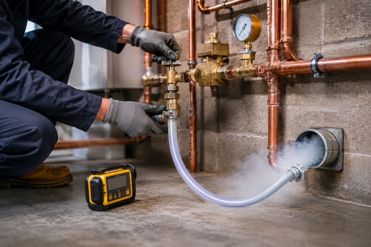
Flexible vent hoses should be positioned securely.
Movement during purging could alter the discharge location and reduce safety.
The hose should remain under the engineer’s control until purging has been completed.
Ignition Source Separation
Discharge points should remain clear of ignition sources throughout the operation.
This includes considering:
- passing vehicles
- building services
- electrical equipment
- members of the public
Maintaining exclusion zones where appropriate further reduces risk.
Equipment Used During Purging
Reliable equipment contributes directly to safe and accurate purging procedures.
Equipment should be inspected before use and maintained in accordance with manufacturer recommendations.
Typical equipment includes:
- pressure gauges
- approved flexible hoses
- purge connections
- combustible gas detectors
- electronic gas analysers
- leak detection fluid
- suitable hand tools
Using calibrated instruments improves the accuracy of testing and commissioning.
Verifying Successful Purging
Completing the purge is not the end of the procedure.
Engineers should verify that the installation is ready for safe appliance operation.
Checks may include:
- confirmation that gas has displaced air
- stable ignition
- consistent flame picture
- satisfactory operating pressure
- successful combustion analysis
- correct appliance operation
Only after these checks have been completed should the installation be considered ready for service.
Purging Errors
Although purging is a routine procedure, mistakes can significantly affect both safety and commissioning.
Engineers should avoid:
- incorrect installation volume calculations
- inaccurate purge volume calculations
- unsuitable discharge locations
- inadequate ventilation
- failure to eliminate ignition sources
- incomplete verification
- poor documentation
Each of these issues can compromise the effectiveness of the purging process and increase unnecessary risk.
Purging Fault Finding
Purging issues are not always immediately obvious during commissioning. Engineers may be called back to investigate ignition problems, unstable flames or appliance lockouts that originate from incomplete purging rather than appliance defects.
A systematic approach to fault finding helps identify whether gas quality, air within the pipework or commissioning procedures are responsible.
Delayed Ignition
Delayed ignition often indicates that residual air remains within sections of the installation.
Where air has not been fully displaced, the appliance may require several ignition attempts before a stable gas supply reaches the burner.
Repeated ignition attempts should not be used as a substitute for correct purging.
Air Locks
Air trapped within branches or appliance connections can interrupt the flow of gas during commissioning.
Symptoms may include:
- failure to ignite
- intermittent burner operation
- unstable flame patterns
- inconsistent gas flow
Further purging of the affected section may be required before normal operation is achieved.
Poor Flame Stability
A burner supplied with a mixture of gas and air may produce:
- lifting flames
- flame instability
- delayed ignition
- incomplete combustion
Before adjusting the appliance, engineers should confirm that purging has been completed successfully.
Repeated Appliance Lockouts
Modern appliances continuously monitor burner operation.
Where combustion remains unstable because of residual air within the installation, safety controls may repeatedly lock out the appliance.
Successful purging often resolves these symptoms without further intervention.
Confirming Cause
Before assuming an appliance fault exists, engineers should verify:
- installation volume calculations
- purge volume calculations
- gas supply stability
- operating pressure
- combustion readings
A logical fault-finding process reduces unnecessary component replacement.
Gas Purging Workflow
Successful purging follows a structured engineering process.
Each stage builds upon the previous one to ensure safety and compliance.
Stage 1
Complete installation work.
↓
Stage 2
Carry out visual inspection.
↓
Stage 3
Complete tightness testing.
↓
Stage 4
Calculate installation volume.
↓
Stage 5
Calculate purge volume.
↓
Stage 6
Complete the risk assessment.
↓
Stage 7
Prepare the discharge location.
↓
Stage 8
Control ignition sources.
↓
Stage 9
Carry out the purging procedure.
↓
Stage 10
Verify gas quality.
↓
Stage 11
Commission the appliance.
↓
Stage 12
Carry out combustion analysis.
↓
Stage 13
Complete documentation.
Following this sequence provides a consistent approach regardless of installation size.
Purging Reference Table
| Situation | Procedure | Verification |
|---|---|---|
| New Installation | Calculate installation volume and purge volume before introducing gas | Gas quality confirmed before commissioning |
| Boiler Replacement | Purge affected pipework after testing | Stable appliance operation |
| Pipework Extension | Recalculate installation volume before purging | Correct purge volume completed |
| Commercial Installation | Follow appropriate IGEM procedures with additional controls where required | Documented commissioning results |
| Repairs | Purge affected section following successful tightness testing | Normal appliance operation restored |
Documentation Requirements
Completing accurate documentation forms an important part of every purging procedure.
It demonstrates that the engineer has followed recognised procedures and provides evidence should future inspections or investigations be required.
Records should include:
- installation address
- installation volume
- purge volume calculation
- tightness testing results
- commissioning checks
- combustion analysis results
- defects identified
- corrective actions taken
- engineer details
- date of completion
Good documentation also supports technical audits and ACS reassessment.
ACS Assessment Expectations
Gas purging forms part of the knowledge expected of engineers undertaking ACS assessments and ACS reassessments.
Candidates should understand both the practical procedures and the engineering principles behind them.
Knowledge Requirements
Engineers should be able to explain:
- the purpose of purging
- installation volume calculations
- purge volume calculations
- safe discharge procedures
- flammable gas mixtures
- commissioning checks
- relevant industry standards
Understanding the reasoning behind each procedure demonstrates technical competence.
Practical Assessment Expectations
Candidates may be expected to:
- calculate installation volume
- determine purge volume
- explain safe venting procedures
- identify hazards
- demonstrate commissioning knowledge
- verify successful purging
Assessors are likely to focus on the engineer’s decision-making process as well as technical accuracy.
Assessment Scenarios
Typical assessment discussions may include:
Scenario One:
A newly installed boiler repeatedly fails to ignite after commissioning.
The candidate should consider incomplete purging before assuming an appliance fault.
Scenario Two:
An engineer extends an existing gas installation.
The assessor asks whether the previous purge calculation remains valid.
The correct response recognises that installation volume has changed and the purge volume should therefore be recalculated.
Scenario Three:
An unsuitable discharge point has been selected.
The candidate should identify the associated hazards and explain how a safer location would be chosen.
Purging Compliance Checklist
| Requirement | Completed |
|---|---|
| Visual inspection completed | ☐ |
| Tightness testing completed | ☐ |
| Installation volume calculated | ☐ |
| Purge volume calculated | ☐ |
| Risk assessment completed | ☐ |
| Discharge location assessed | ☐ |
| Ignition sources controlled | ☐ |
| Purging completed | ☐ |
| Gas quality verified | ☐ |
| Appliances commissioned | ☐ |
| Combustion analysis completed | ☐ |
| Documentation completed | ☐ |
Gas Training Courses In Staffordshire
Gas purging is an essential engineering procedure that supports safe commissioning, reliable appliance operation and compliance with current industry standards. It sits alongside gas soundness testing, tightness testing and combustion analysis as one of the core competencies expected of Gas Safe registered engineers.
At Staffordshire Training Services, engineers can strengthen their technical knowledge through accredited training, ACS assessments and reassessments that reflect current industry procedures and recognised standards. Gas training courses cover key areas including gas soundness, purging procedures, pipework installation, combustion analysis, fault finding and technical updates, helping engineers maintain competence throughout their careers.
Continuing professional development enables engineers to remain current with changes to legislation, IGEM procedures and industry guidance while reinforcing the practical skills required to work safely and confidently.
Safe Purging Protects Every Gas Installation
Gas purging is far more than a commissioning task. It is a controlled engineering process that prevents hazardous gas and air mixtures, prepares installations for safe operation and provides the foundation for reliable appliance performance.
Accurate installation volume calculations, correct purge volume determination, careful risk assessment and effective verification all contribute to a successful outcome. When these procedures are combined with thorough testing, combustion analysis and accurate documentation, engineers can commission installations with confidence while maintaining compliance with current gas industry standards.
By understanding both the theory and practical application of gas purging, engineers strengthen their technical competence, improve the quality of their work and continue to uphold the high standards expected across the gas industry.
Related Articles
- Gas Tightness Testing Fault-Finding Techniques
- Gas Pipework Installation Standards For Gas Engineers
- Gas Pressure Testing and Appliance Performance For Engineers
- Combustion Analysis and Flue Gas Testing For Gas Engineers
- Gas Pressure, Flow, Tightness Testing and Purging Explained
Prefer an AI Summary?