
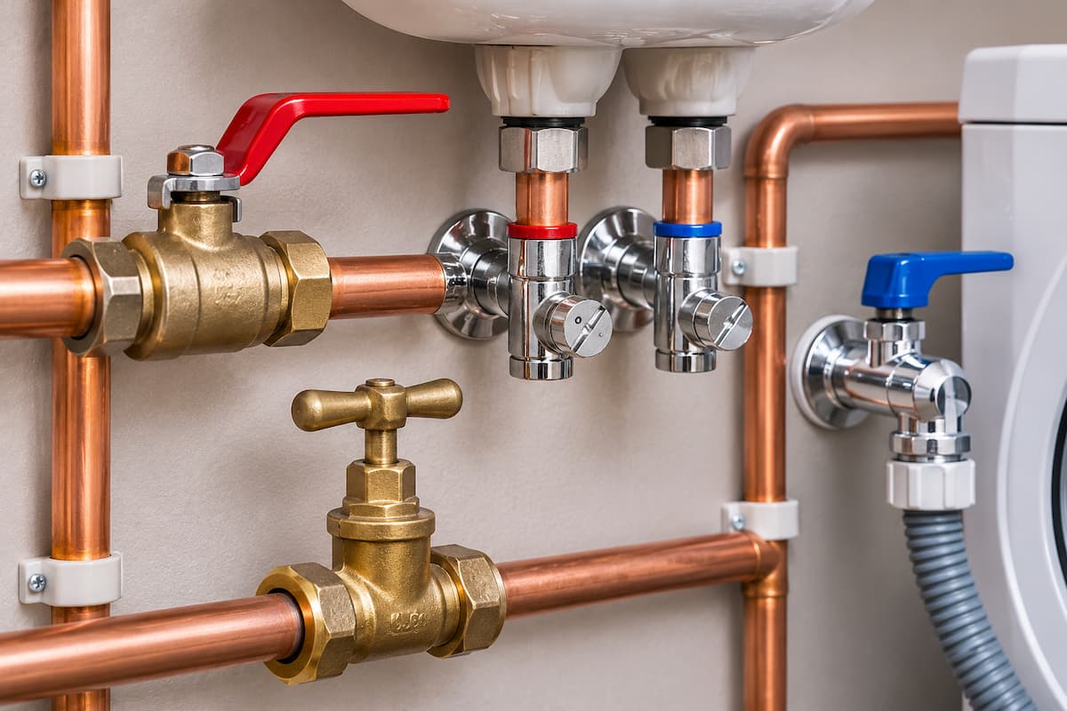
Isolation and service valves are essential components of domestic plumbing systems, allowing engineers to shut off the water supply to individual appliances, outlets or sections of pipework without necessarily interrupting the supply to the entire property.
Although relatively simple in construction, these valves have an important role in the operation and maintenance of plumbing installations. An incorrectly selected valve can restrict water flow, while a poorly positioned or defective valve can make routine servicing difficult and increase the risk of water damage.
For plumbers and heating engineers, understanding the differences between isolation valves, service valves, ball valves and stop taps is an important part of designing, installing and maintaining reliable domestic water supplies.
This article examines valve construction, operating principles, flow characteristics, installation requirements, maintenance and practical fault diagnosis, including their relationship with water pressure and the Water Supply (Water Fittings) Regulations.
Isolation Valves
An isolation valve is installed within pipework to allow the flow of water to be stopped when necessary.
In domestic plumbing, isolation valves are commonly positioned close to appliances and sanitary fittings so that maintenance or replacement work can be carried out without draining or isolating a larger section of the installation.
Typical applications include:
- Isolating basin and sink taps
- Shutting off the supply to toilet cisterns
- Isolating washing machines and dishwashers
- Providing maintenance isolation for shower supplies
- Separating sections of hot and cold water distribution pipework
- Allowing individual components to be serviced or replaced
A properly positioned isolation valve reduces the amount of water that needs to be drained and limits disruption to other occupants.
Within the wider arrangement of domestic plumbing systems, isolation valves also make it easier to maintain individual components without unnecessarily interrupting other supplies.
However, the presence of an isolation valve does not guarantee that a component is safe to remove. The valve must provide effective shut-off, and any remaining pressure or stored water must be dealt with before work begins.
Isolation Valves and Service Valves
The terms isolation valve and service valve are often used interchangeably in domestic plumbing, although they can describe slightly different applications.
An isolation valve is a general term for a valve used to stop flow through a section of pipework.
A service valve is typically a smaller valve installed close to an appliance or fitting to allow that particular component to be isolated for maintenance.
For example, a service valve may be fitted beneath a washbasin to isolate the cold water supply to the tap. In contrast, a larger lever-operated ball valve may be installed on a distribution branch to isolate several outlets.
Both provide isolation, but their construction, operating mechanism and flow characteristics may differ.
Types Of Isolation Valves
Several valve designs are used in domestic plumbing installations. The most suitable type depends on the application, pipe diameter, required flow rate, available installation space and operating conditions.
Screwdriver Operated Service Valves
Screwdriver operated service valves are commonly fitted to small diameter domestic pipework.
They normally incorporate a slotted operating spindle that can be turned using a screwdriver.
Many designs use a quarter-turn mechanism, allowing the valve to move between fully open and fully closed positions.
These valves are frequently installed beneath basins, behind toilets and near other individual appliances.
Their compact design makes them convenient where installation space is limited. However, some standard service valves have a relatively narrow internal passage, which can create additional resistance to water flow.
Lever Operated Ball Valves
Lever-operated ball valves use a spherical internal component with a passage through its centre.
Rotating the lever turns the ball, aligning the passage with the pipework when open and blocking the passage when closed.
Most domestic ball valves operate through a quarter turn.
The lever normally indicates the operating position:
- Lever parallel to the pipe indicates the valve is open.
- Lever perpendicular to the pipe indicates the valve is closed.
Lever-operated ball valves are commonly used where frequent operation, reliable isolation or a larger flow passage is required.
They are available in different materials, connection types and bore sizes.
Full Bore Isolation Valves
A full bore isolation valve has an internal opening designed to be approximately equivalent to the nominal internal passage of the associated pipework or valve connection.
This reduces the restriction created by the valve compared with a reduced bore design.
Full bore valves can be particularly useful where maintaining available flow is important, including some shower supplies and distribution pipework.
However, the term full bore does not guarantee zero pressure loss. Actual hydraulic performance depends on the manufacturer’s design and the resistance created by the valve body, connections and internal passage.
Stop Valves and Stop Taps
Stop valves are commonly used to control the water supply entering a property or supplying a substantial section of the installation.
A traditional stop tap generally uses a threaded spindle and washer arrangement.
Turning the operating head moves the internal mechanism towards or away from its seating, controlling the flow of water.
Unlike a quarter-turn ball valve, a traditional stop tap usually requires several turns to open or close.
Stop taps are commonly associated with the incoming mains supply, although their exact position and arrangement vary between properties.
Appliance Isolation Valves
Washing machines and dishwashers commonly use dedicated appliance valves.
These often incorporate a threaded outlet suitable for connecting an appliance hose.
Some designs use a small lever, while others use a screwdriver-operated mechanism.
The valve must be compatible with the appliance connection and suitable for the operating pressure and temperature of the water supply.
An appliance valve provides a convenient means of isolation, but it should remain accessible for operation and maintenance.
Isolation Valve Construction
Although valve designs vary, most domestic isolation valves contain several basic components.
These include:
- Valve body
- Internal closing mechanism
- Operating spindle
- Seals or seats
- Operating lever, handle or slot
- Pipe connections
In a ball valve, the internal ball rotates between sealing seats.
In a traditional stop valve, the operating spindle moves a washer or disc towards the valve seat.
The condition of these internal components determines whether the valve can provide effective isolation.
Damage, contamination, wear or corrosion may prevent the mechanism from closing correctly.
Full Bore and Reduced Bore Valves
One of the most important considerations when selecting an isolation valve is the size of its internal water passage.
Two valves with the same nominal connection size may have significantly different internal bore dimensions.
For example, a valve suitable for connection to 15 mm copper pipe may have a smaller internal passage than the pipe itself.
This creates a local restriction. As water passes through the narrowed opening, its velocity increases and additional pressure loss occurs. The effect becomes more significant as flow increases.
A reduced bore valve may be suitable for a toilet cistern or a low-demand basin tap, but it may be less appropriate where a higher flow rate is required.
The choice should therefore reflect the hydraulic requirements of the connected outlet rather than simply matching the nominal pipe diameter.
Pressure Loss Across Isolation Valves
Water flowing through a valve experiences resistance caused by changes in direction, changes in passage size and friction within the valve.
This resistance produces a pressure difference between the inlet and outlet while water is flowing.
The pressure loss depends on:
- Flow rate
- Internal bore
- Valve design
- Degree of opening
- Water velocity
- Connection geometry
A valve with a smaller internal passage will generally create greater resistance than a comparable full bore valve under the same conditions.
However, the actual pressure loss should be established using manufacturer performance information rather than relying on appearance alone.
For engineers working with restricted water supplies, the distinction between static pressure and pressure available during flow is particularly important. As covered in our guide to understanding water pressure in plumbing systems, pressure and flow must be assessed together when diagnosing restrictions within domestic pipework.
Valve Flow Coefficients
Manufacturers may provide a flow coefficient, commonly expressed as Kv, to describe the hydraulic capacity of a valve.
Kv represents the flow rate of water in cubic metres per hour that produces a pressure drop of 1 bar across the valve under defined reference conditions.
For water, an approximate relationship is:
Q = Kv × √Δp
Where:
- Q is the flow rate in m³/h.
- Kv is the valve flow coefficient.
- Δp is the pressure drop in bar.
For example, a valve with a Kv value of 2.0 operating with a pressure drop of 0.25 bar would have an approximate flow rate of:
Q = 2.0 × √0.25
Q = 1.0 m³/h
This is equivalent to approximately 16.7 litres per minute.
The calculation illustrates the relationship between flow and pressure loss. Actual valve selection should use the manufacturer’s published performance data and the operating requirements of the installation.
Comparing Domestic Isolation Valves
| Valve Type | Operating Mechanism | Typical Application | Flow Considerations |
|---|---|---|---|
| Standard service valve | Screwdriver operated, commonly quarter turn | Basins, toilets and individual fittings | Some designs have a restricted internal bore |
| Full bore service valve | Quarter turn mechanism | Individual outlets where higher flow is required | Generally offers less restriction than comparable reduced bore designs |
| Lever operated ball valve | Quarter turn lever | Distribution branches and maintenance isolation | Available in full bore and reduced bore configurations |
| Traditional stop tap | Multi turn spindle and washer | Incoming mains and supply isolation | Flow resistance depends on valve design and opening |
| Appliance valve | Lever or screwdriver operation | Washing machines and dishwashers | Must be suitable for appliance demand and connection |
Selecting Isolation Valves For Domestic Plumbing
Valve selection should take into account more than pipe diameter.
The engineer must establish whether the valve is suitable for the water supply, operating conditions and intended maintenance function.
Important considerations include:
- Nominal pipe and connection size
- Maximum working pressure
- Permitted operating temperature
- Flow capacity
- Valve body material
- Seal compatibility
- Connection method
- Accessibility
- Suitability for wholesome water
A valve suitable for a cold water supply is not automatically suitable for every hot water or heating application.
Manufacturer specifications should be checked before installation.
Isolation Valves On Hot and Cold Water Supplies
Isolation valves are commonly installed on both hot and cold domestic water distribution pipework.
The arrangement of the incoming supply can influence the position and selection of these valves. In direct and indirect water supply systems, differences in supply pressure and distribution arrangements may affect the type of valve required and its position within the installation.
The operating temperature is another important consideration because seals, plastics and other internal materials have specified temperature limits.
Valves installed on hot water supplies must be suitable for the temperatures that may occur during normal operation and foreseeable system conditions.
This is particularly relevant near hot water cylinders, where stored water temperatures may be higher than the temperature delivered at individual outlets.
Where a thermostatic mixing valve is installed, suitable upstream isolation can make maintenance and replacement easier.
The isolation arrangement must not interfere with required safety devices or create an unsafe condition.
Isolation Valves On Basin and Sink Taps
Service valves are commonly installed beneath basins and sinks to allow individual taps to be maintained or replaced.
Separate valves are generally provided on the hot and cold supplies.
This arrangement allows the engineer to isolate the fitting without necessarily interrupting the water supply to other outlets.
Where flexible tap connectors are used, some service valves incorporate a connection suitable for the flexible hose.
The valve should be positioned so that the operating mechanism remains accessible and the connecting pipework is adequately supported.
A valve hidden behind fixed furniture or inaccessible panels may be difficult to operate during an emergency or routine repair.
Isolation Valves On Toilet Cisterns
Toilet cisterns are commonly supplied through a small service valve positioned near the inlet connection.
The valve allows the filling valve or cistern components to be maintained without isolating the entire cold water system.
A standard reduced bore service valve may be suitable where the cistern filling requirements can be met.
However, the selected valve must not restrict the supply to the extent that filling performance becomes unacceptable.
The engineer should also check that the valve and associated connections remain accessible after the toilet has been installed.
Isolation Valves On Shower Supplies
Shower installations can be particularly sensitive to pressure loss and restrictions in the hot and cold supplies.
Where isolation valves are fitted upstream of a shower valve, their hydraulic characteristics should be considered alongside the shower manufacturer’s requirements.
A reduced bore service valve may introduce an unnecessary restriction, particularly in systems with limited available pressure.
Full bore isolation valves may be more appropriate where maintaining flow is important.
Both supplies should be considered together because excessive differences in supply conditions can affect the operation of some shower mixing valves.
The final selection should reflect the shower design, water supply arrangement and manufacturer instructions.
Isolation Valves Around Hot Water Cylinders
Hot water cylinders incorporate several connections that may require isolation for maintenance.
These can include the incoming cold water supply, associated distribution pipework and certain serviceable components.
However, the position and function of each valve must be considered carefully.
In particular, isolation valves must not be installed or operated in a way that compromises the operation of required expansion or pressure relief arrangements.
For unvented hot water cylinders, the manufacturer’s approved installation arrangement must be followed.
The presence of an isolation valve does not remove the need to depressurise the system and follow the correct servicing procedure before removing components.
Isolation Valves On Cold Water Storage Systems
Properties with stored cold water supplies may require isolation at the cistern inlet and on individual distribution branches.
The position of these valves depends on the arrangement of the system and the components requiring maintenance.
For example, isolation of the incoming supply to a storage cistern can allow work on the inlet control valve, while separate downstream isolation may be necessary when maintaining connected pipework.
In systems incorporating cold water storage cisterns, engineers must also account for the stored volume of water and the static head available to downstream outlets.
Closing the inlet supply does not immediately remove the water already stored within the cistern.
Appropriate draining and isolation procedures are therefore required before working on connected components.
Isolation Valve Installation
Correct installation is essential to reliable valve operation.
The engineer should first confirm that the selected valve is suitable for the pipework and intended operating conditions.
The installation position should provide sufficient clearance for the valve body, connections and operating mechanism.
The pipework should be properly aligned and supported to avoid placing unnecessary mechanical stress on the valve.
Common connection arrangements include:
- Compression fittings
- Push fit connections
- Threaded connections
- Press fit connections
Not every valve is available or approved for every connection method.
The manufacturer’s installation instructions should determine the correct fitting procedure.
Compression Isolation Valves
Compression isolation valves are widely used with copper pipework.
A typical compression connection incorporates a compression nut and olive that form a seal when correctly assembled and tightened.
The pipe must be cut cleanly and inserted to the required depth.
Excessive tightening can damage the fitting or pipe, while insufficient tightening may result in leakage.
The valve should be supported during tightening to prevent twisting or stressing adjacent pipework.
Where plastic pipe is connected to a compression fitting, the pipe and fitting manufacturer’s requirements for inserts and compatibility must be followed.
Push Fit Isolation Valves
Push fit isolation valves are used with compatible plastic or copper pipework.
These connections generally rely on internal seals and retaining components to secure the pipe.
Successful installation depends on correct pipe preparation, insertion depth and compatibility.
The pipe must be cut squarely, free from damage and inserted fully into the fitting.
Where required, suitable pipe inserts must be installed.
Some push fit systems also incorporate locking or release mechanisms that must be operated according to the manufacturer’s instructions.
Valve Orientation and Accessibility
Some isolation valves can be installed in different orientations, while others have manufacturer-specified flow direction requirements.
Where a directional arrow is marked on the valve body, the installation must follow the manufacturer’s instructions.
Accessibility is equally important.
An isolation valve should be positioned so that it can be operated when maintenance is required.
Cabinets, pipework, appliances or building finishes should not obstruct the operating mechanism.
Where valves are installed behind access panels, the panels should provide sufficient access for operation and servicing.
Commissioning Isolation Valves
After installation, the valve and its connections should be checked before the plumbing system is returned to normal use.
Commissioning should include:
- Confirming that the valve is correctly installed and supported.
- Checking the direction of flow where applicable.
- Restoring the water supply gradually.
- Inspecting the valve body and connections for leakage.
- Operating the valve through its intended movement.
- Confirming that the valve opens fully.
- Checking that it provides effective isolation when closed.
- Verifying satisfactory flow when reopened.
Testing should be appropriate to the installation and the manufacturer’s requirements.
Where a valve has been installed as part of a larger alteration, the relevant section of the water system must also be tested and commissioned.
Isolation Valve Maintenance
Isolation valves are often left in the open position for extended periods.
Over time, internal deposits, corrosion or deterioration of seals may affect their operation.
A valve that has not been operated for several years may become difficult to close or may fail to provide complete isolation.
Routine inspection should consider:
- Ease of operation
- Signs of external leakage
- Condition of the operating spindle
- Corrosion or deposits
- Valve accessibility
- Ability to provide effective shut off
Where operation is recommended by the manufacturer or maintenance programme, the valve should be exercised carefully and checked for leakage.
Excessive force should not be applied to a seized valve because the spindle or internal mechanism may fail.
Isolation Valve Fault Finding and Diagnosis
Isolation valve faults generally involve incomplete shut-off, restricted water flow, external leakage or difficulty operating the valve. Establishing the cause requires an assessment of the valve itself and the wider water supply arrangement.
A valve that allows water to pass while fully closed is commonly described as a passing valve. This may result from damaged sealing surfaces, debris trapped within the mechanism, worn washers or incomplete valve movement.
Valves can also become difficult to operate after prolonged periods without use. Scale deposits, corrosion and deterioration of internal components may restrict movement, while excessive force can damage the spindle or operating mechanism.
External leaks may develop around compression connections, spindle seals or the valve body. The leak’s location helps identify whether the problem involves the connection, internal sealing components, or mechanical damage.
Restricted Water Flow
A reduced flow rate at a tap or appliance may indicate a partially closed or restricted isolation valve, although other components can produce similar symptoms.
Possible causes include:
- Partially closed isolation valves
- Reduced bore fittings
- Debris trapped within the valve
- Blocked tap aerators or strainers
- Restricted flexible hoses
- Pipework restrictions
- Insufficient available supply pressure
The engineer should establish whether the problem affects one outlet or several outlets. A restriction affecting a single fitting may indicate a local fault, while reduced performance across multiple outlets can suggest a problem further upstream.
Pressure and flow measurements can help identify the location of the restriction. Where a pressure reducing valve is installed upstream, its operation may also need to be assessed.
Replacing an isolation valve without confirming the source of the restriction may not resolve the problem.
Isolation Valve Fault Diagnosis Table
| Symptom | Possible Cause | Diagnostic Focus |
|---|---|---|
| Valve does not fully isolate | Damaged seats, debris, worn washer or incomplete closure | Confirm valve position and establish whether water continues to pass |
| Valve difficult to operate | Scale, corrosion or internal seizure | Assess spindle movement and condition without applying excessive force |
| Leak around spindle | Worn or damaged spindle seal | Identify the leakage point and establish whether the valve can be serviced |
| Leak at pipe connection | Incorrect assembly, damaged seal, pipe damage or fitting movement | Inspect the connection, pipe alignment and support |
| Low flow through outlet | Reduced bore valve, partial closure, debris or another supply restriction | Compare flow and pressure conditions and check other potential restrictions |
| Operating handle damaged | Excessive force, wear or mechanical damage | Determine whether the valve can still be operated reliably |
| Valve leaks after operation | Deteriorated seals or internal components | Inspect the valve and establish whether repair or replacement is appropriate |
Repair and Replacement
Not every isolation valve is designed to be dismantled or repaired. Where internal components have deteriorated, or the valve cannot provide reliable isolation, replacement may be the most practical solution.
Before removing a defective valve, the water supply must be isolated at another suitable point, and the affected pipework depressurised.
The replacement valve should be selected according to the pipework, operating pressure, temperature and required flow capacity.
Following installation, the engineer should confirm that the valve operates correctly, provides effective shut-off and remains free from leakage under normal operating conditions.
Isolation Valves and Water Regulations
Isolation valves installed on domestic water supplies must be suitable for their intended use and comply with the applicable Water Supply (Water Fittings) Regulations.
These requirements are intended to protect the quality of wholesome water and prevent waste, misuse, undue consumption and contamination.
The requirements are particularly relevant to the selection of fittings used on wholesome water supplies. The wider responsibilities associated with compliant plumbing installations are covered in our article on water regulations and their importance for plumbers.
Valve materials and construction must be appropriate for contact with the water being supplied.
Where relevant, engineers should check that products have suitable evidence of compliance, such as appropriate certification or approval.
The valve must also be installed in a way that does not create an avoidable risk of contamination or interfere with the proper operation of the water system.
Isolation Valves and Backflow Prevention
An isolation valve is not the same as a backflow prevention device.
An isolation valve is intended to stop water flow when operated.
A backflow prevention device is designed to prevent water from flowing in an unintended direction under specified conditions.
Although an isolation valve may be closed to separate a section of pipework, it should not be relied upon as a substitute for the required backflow protection.
The correct protective arrangement depends on the fluid category, installation conditions and applicable water regulations.
For example, an appliance connection may require suitable backflow protection in addition to an isolation valve.
The presence of a service valve does not remove that requirement.
Isolation Valves In Plumbing System Design
The position of isolation valves should be considered during the initial design of a plumbing installation rather than added only where convenient.
A designed arrangement allows individual fittings or sections of pipework to be maintained without unnecessarily interrupting other supplies.
However, installing additional valves also introduces more connections and potential leakage points.
The aim is therefore to provide practical and reliable isolation without creating unnecessary complexity.
Engineers should consider:
- Which components will require routine servicing
- The sections of pipework that may need isolation
- Access to the operating mechanism
- Required flow performance
- Valve compatibility
- Future maintenance and replacement
These considerations are particularly relevant in larger domestic properties with multiple bathrooms, separate hot water distribution branches or complex plumbing arrangements.
Plumbing Training In Staffordshire
Isolation and service valves may be relatively small components, but correct selection and installation depend on a sound understanding of water supply systems, flow characteristics, materials and regulatory requirements.
Plumbers must be able to identify suitable fittings, install them correctly, assess their performance and recognise faults that could affect the reliability of the wider plumbing installation.
At Staffordshire Training Services, the Water Regulations Certificate provides relevant training in water supply requirements, water fittings and the prevention of contamination.
For engineers working with stored hot water systems, the Hot Water Systems and Safety Course develops knowledge of domestic hot water arrangements, including the safety considerations associated with installation and maintenance.
Delivered at our dedicated training centre in Stafford, our accredited courses support plumbers and heating engineers in developing the technical knowledge and practical confidence needed to work competently across domestic plumbing systems.
Related Articles
- Thermostatic Mixing Valves in Domestic Plumbing Systems
- Pressure Reducing Valves in Domestic Plumbing Systems
- Expansion Vessels In Domestic Plumbing and Heating Systems
- Unvented Hot Water Cylinders In Domestic Plumbing
- Vented Hot Water Systems In Domestic Plumbing
Prefer an AI Summary?