Modern gas appliances incorporate multiple safety devices designed to prevent uncontrolled gas release, verify safe combustion and protect both occupants and property. While these components often operate unnoticed during normal appliance use, they perform critical functions every time an appliance starts, operates and shuts down.
Gas engineers must understand not only how these safety devices function, but also how they interact with one another throughout the appliance operating sequence. A fault with a flame sensor, thermocouple, gas valve, or air pressure switch can prevent an appliance from operating correctly. At the same time, a failure of a safety device may pose significant risks if not identified during servicing or fault-finding.
As appliances become increasingly sophisticated, engineers are expected to diagnose faults using electrical testing, combustion analysis, and logical fault-finding techniques rather than replacing components by trial and error. Understanding flame supervision systems is therefore an essential part of modern gas engineering competence and features prominently within ACS assessments and manufacturer training.
This article examines the operation, testing and diagnosis of flame supervision systems and gas safety devices, helping engineers understand both the engineering principles and practical procedures involved in maintaining safe appliance operation.
Gas Safety Standards and Regulations
Gas appliance safety devices are not optional components. They form part of the appliance’s certified safety design and must always remain operational throughout its service life.
Several pieces of legislation, British Standards and industry guidance govern their installation, testing and maintenance.
Gas Safety (Installation And Use) Regulations
The Gas Safety (Installation and Use) Regulations require every gas appliance to be installed and maintained so that it operates safely.
This includes ensuring that:
- safety devices function correctly
- combustion remains safe
- gas is shut off automatically when faults occur
- defective components are identified and rectified
- appliances are not returned to service with compromised safety controls
Bypassing or turning off a safety device is never acceptable and may constitute unsafe gas work.
British Standards
Several British Standards support the safe installation and maintenance of gas appliances.
Depending on the appliance type, engineers may refer to standards covering:
- domestic gas fired boilers
- combustion performance
- commissioning procedures
- servicing requirements
- installation practices
These standards work alongside manufacturer instructions to ensure appliances continue operating safely.
Manufacturer Instructions
Every appliance manufacturer specifies procedures for:
- commissioning
- servicing
- flame supervision testing
- component replacement
- electrical testing
- combustion analysis
Manufacturers may also specify acceptable electrical values for flame detection circuits, thermocouples and other safety components.
These instructions should always be followed when diagnosing or repairing faults.
Gas Safe Technical Guidance
Gas Safe Register Technical Bulletins and current industry guidance provide additional advice where installation practices or safety procedures are updated.
Keeping current with these publications forms an important part of continuing professional development.
The Purpose of Flame Supervision Systems
Every gas appliance requires a reliable method to confirm that combustion has been established before gas continues to flow to the burner.
Flame supervision systems provide this confirmation.
If the flame disappears unexpectedly, the system automatically shuts off the gas supply within seconds, preventing unburnt gas from accumulating inside the appliance or on the surrounding property.
Without flame supervision, relatively minor faults could quickly develop into extremely dangerous situations.
Preventing Uncontrolled Gas Release
The primary purpose of flame supervision is to ensure that gas flows only when a stable flame is present.
If ignition fails or the flame is extinguished because of:
- wind disturbance
- blocked burners
- low gas pressure
- component failure
- interrupted gas supply
The appliance immediately closes the gas valve.
This automatic response significantly reduces the risk of gas escaping into occupied spaces.
Protecting Occupants
Effective flame supervision protects occupants against hazards including:
- gas accumulation
- explosion
- fire
- incomplete combustion
- carbon monoxide production
The rapid operation of these systems is one of the most important safety features found within modern gas appliances.
Supporting Safe Combustion
Stable combustion depends upon:
- correct gas pressure
- suitable air supply
- reliable ignition
- consistent flame detection
Flame supervision provides continuous confirmation that these conditions persist throughout the appliance’s operation.
The Complete Appliance Safety Chain
Modern appliances rely on several independent safety devices working together rather than a single protective component.
Each stage must operate successfully before the next begins.
The sequence typically follows this order:
Heat demand received
↓
Electronic controls perform initial safety checks
↓
Fan starts where applicable
↓
Air pressure switch confirms airflow
↓
Ignition sequence begins
↓
Gas valve opens
↓
Burner ignites
↓
Flame supervision system confirms flame presence
↓
Appliance continues normal operation
↓
Continuous monitoring during operation
↓
Flame lost or unsafe condition detected
↓
Gas valve closes automatically
↓
Appliance enters safety lockout if required
Understanding this sequence allows engineers to diagnose faults logically rather than replace components unnecessarily.
Types Of Flame Supervision Devices
Different appliance designs use different methods to confirm the presence of a flame.
The choice depends on the appliance type, burner design, and operating environment.
Thermocouples
Thermocouples remain widely used in appliances that incorporate permanent pilot flames.
They generate a small electrical voltage when heated by the pilot flame, allowing the gas valve to remain open.
Loss of the pilot flame causes the voltage to fall, releasing the safety magnet and shutting off the gas supply.
Although relatively simple, thermocouples remain highly reliable when correctly installed.
Flame Rectification Systems
Most modern domestic boilers no longer use permanent pilots.
Instead, electronic flame rectification systems confirm that the main burner has ignited successfully.
These systems detect a very small electrical current passing through the flame and back to the appliance control board.
If the signal disappears, the PCB immediately closes the gas valve and begins the lockout sequence.
Flame rectification offers rapid response times and continuous monitoring throughout burner operation.
Ionisation Probes
Ionisation probes form part of many flame rectification systems.
The probe sits within the burner flame and detects the ionisation current produced during combustion.
The control board continuously monitors this signal to verify flame stability.
Dirty probes, poor earthing, or unstable combustion can all reduce signal strength and cause nuisance lockouts.
Optical Flame Detection
Larger industrial burners may use optical sensors that detect visible light produced by combustion.
These systems are generally used where direct flame contact with a probe is impractical.
Ultraviolet Flame Sensors
Some commercial and industrial burners use ultraviolet sensors.
These detectors monitor ultraviolet radiation emitted by stable flames and enable rapid flame-failure detection in larger combustion systems.
Infrared Flame Sensors
Infrared flame sensors operate by detecting infrared energy generated during combustion.
They are commonly found on specialist industrial combustion equipment where larger burners require continuous monitoring.
Flame Supervision Systems Comparison Table
| System | Typical Application | Detection Method | Advantages | Typical Faults |
|---|---|---|---|---|
| Thermocouple | Pilot flame appliances | Millivolt generation | Simple and reliable | Weak output, poor flame contact |
| Flame Rectification | Modern domestic boilers | Ionisation current | Fast response and continuous monitoring | Poor earth, dirty sensor, PCB faults |
| Ionisation Probe | Electronic burner systems | Microamp flame signal | Highly accurate flame detection | Contamination, damaged probe |
| UV Sensor | Commercial burners | Ultraviolet radiation | Rapid flame detection | Sensor contamination |
| Infrared Sensor | Industrial combustion systems | Infrared radiation | Suitable for large burners | Alignment or sensor faults |
Thermocouples
Thermocouples are widely used as flame supervision devices on gas appliances fitted with permanent pilot flames. Their purpose is to prove that the pilot flame is established before allowing the gas valve to remain open.
A thermocouple consists of two dissimilar metals joined at the sensing tip. When the pilot flame heats this junction, it generates a small direct-current voltage via the Seebeck effect. This electrical output energises an electromagnet within the gas valve, holding the safety valve open while the flame remains established.
If the pilot flame is extinguished, the thermocouple begins to cool. Its electrical output falls until the electromagnet can no longer hold the valve open. The valve then closes, preventing unburnt gas from entering the appliance. Flame supervision devices are designed to shut off the gas supply automatically following flame failure.
Thermocouple Operating Sequence
The operating sequence normally follows these stages:
1. The appliance control is pressed and held.
2. Gas flows to the pilot burner.
3. The pilot flame is ignited.
4. The flame heats the thermocouple tip.
5. The thermocouple generates a small electrical voltage.
6. The gas valve electromagnet becomes energised.
7. The control is released, and the pilot gas supply remains open.
8. Flame failure causes the thermocouple to cool.
9. The magnet releases and the gas supply closes.
The precise hold-in and release times depend on the appliance design, thermocouple condition and manufacturer specification.
Thermocouple Positioning
Correct positioning is essential. The sensing tip must sit within the correct part of the pilot flame to receive sufficient heat without being damaged by excessive heat.
A thermocouple positioned outside the pilot flame may produce insufficient output. One positioned too deeply may deteriorate prematurely.
Engineers should inspect:
- the position of the sensing tip
- pilot flame size and stability
- contamination around the pilot burner
- damage to the thermocouple sheath
- security of the connection at the gas valve
The manufacturer’s instructions should determine the correct location and testing procedure.
Thermocouple Fault Symptoms
A weak or failed thermocouple may produce symptoms including:
- pilot flame failing to remain established
- pilot extinguishing when the control is released
- intermittent pilot failure
- extended hold-in time
- appliance shutdown after warming or cooling
These symptoms do not prove that the thermocouple itself has failed. A weak pilot flame, a contaminated pilot injector, poor thermocouple positioning, or a defective gas valve magnet may produce similar behaviour.
Testing Thermocouple Output
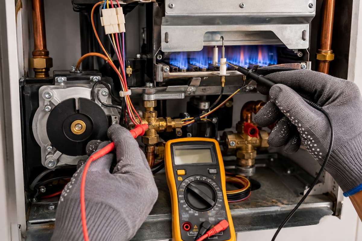
Thermocouple testing should be carried out using a suitable digital multimeter capable of measuring millivolts.
The engineer should follow the appliance manufacturer’s instructions because expected values and test arrangements vary between appliances.
Open Circuit Testing
An open circuit test measures the voltage produced by the thermocouple without the gas valve magnet connected.
The general process involves:
1. Isolating the appliance safely.
2. Disconnecting the thermocouple from the gas valve where permitted.
3. Connecting the multimeter using an appropriate adaptor.
4. Lighting the pilot in accordance with the manufacturer’s procedure.
5. Allowing the thermocouple to reach operating temperature.
6. Recording the millivolt output.
7. Comparing the result with the manufacturer’s specification.
A low open circuit reading may indicate:
- inadequate pilot flame
- poor thermocouple positioning
- contamination
- thermal damage
- deterioration of the thermocouple junction
Closed Circuit Testing
A closed circuit test measures the thermocouple output while it remains connected to the gas valve magnet.
This provides a better indication of performance under operating load.
The result can help distinguish between:
- weak thermocouple output
- excessive resistance
- a defective interrupter
- a failing gas valve magnet
Numerical pass values should not be applied universally. Engineers must use appliance-specific data because thermocouple systems, magnets, and interrupter circuits vary between manufacturers.
Worked Thermocouple Example
An appliance’s pilot light ignites correctly but extinguishes as soon as the control is released.
The engineer confirms that:
- the pilot flame is stable
- the thermocouple is positioned correctly
- the pilot injector is clear
- the thermocouple connection is secure
The measured thermocouple output remains below the appliance manufacturer’s specified value after the required heating period.
This evidence supports replacing the thermocouple rather than adjusting the gas valve or replacing unrelated components.
Following replacement, the engineer should verify:
- reliable pilot retention
- correct flame failure response
- gas soundness at disturbed joints
- safe appliance operation
Flame Rectification Systems
Flame rectification is the principal method of flame supervision used in many modern electronic gas appliances.
Rather than relying on heat generated by a permanent pilot flame, the system uses the electrical properties of an established burner flame.
A flame contains ionised particles and can conduct a very small electrical current. The flame rectification circuit applies an alternating electrical potential between the flame sensing electrode and the burner earth. The flame allows current to flow more readily in one direction, creating a small direct-current signal that the appliance’s PCB can monitor.
When a sufficient flame signal is detected, the PCB keeps the gas valve energised. If the signal falls below the appliance’s required level, the control closes the gas valve and may initiate a further ignition attempt or safety lockout.
Flame Signal Requirements
The flame signal is normally measured in microamps. The acceptable value depends on:
- appliance design
- burner construction
- electrode position
- control board specification
- flame quality
- manufacturer requirements
Engineers should never apply a single universal microamp value to every appliance. The installation and servicing instructions remain the primary reference for acceptable readings and test procedures. Boiler manufacturers publish appliance specific installation and servicing literature for this purpose. ([Worcester Bosch][2])
Earth Path Importance
Flame rectification relies on a complete electrical path through:
- the flame sensing electrode
- the burner flame
- the burner assembly
- appliance earth
- the PCB
Poor earthing can prevent the control board from recognising a flame even though the burner has ignited.
Possible causes include:
- loose earth connections
- corrosion
- damaged wiring
- contaminated burner surfaces
- incorrect polarity
- poor PCB connections
Before replacing a flame-sensing electrode or control board, engineers should verify the entire flame-signal circuit.
Ionisation Probe Testing
An ionisation probe should be inspected before electrical measurements are taken.
The engineer should assess:
- probe condition
- ceramic insulation
- electrode position
- lead condition
- electrical connections
- burner earth continuity
Cracked ceramic insulation may allow the signal to leak away. A bent electrode may sit outside the correct flame area, while oxidation or combustion deposits can reduce the available signal.
Microamp Testing
Where permitted by the manufacturer, the flame current can be measured by placing a suitable multimeter in series with the ionisation lead.
The general process is:
1. Isolate the electrical supply.
2. Access the flame sensing circuit.
3. Configure the meter for direct current microamps.
4. Connect the meter in series with the ionisation lead.
5. Restore the appliance supply.
6. Initiate a heat demand.
7. Record the flame current after ignition.
8. Compare the reading with manufacturer data.
9. Isolate the appliance before removing the meter.
Incorrect meter connection can interrupt the flame signal or damage equipment. Engineers should use suitable test leads and follow manufacturer instructions.
Interpreting A Weak Flame Signal
A weak ionisation current may result from:
- contaminated flame electrode
- incorrect electrode position
- poor earth continuity
- unstable burner flame
- incorrect gas pressure
- blocked burner ports
- combustion air problems
- damaged wiring
- failing PCB input circuit
Cleaning or replacing the probe without investigating combustion conditions may leave the underlying fault unresolved.
Worked Flame Rectification Example
A boiler lights successfully but enters lockout several seconds later.
Visual inspection confirms that a flame is present. The engineer then checks:
- polarity
- earth continuity
- ionisation lead condition
- probe position
- burner cleanliness
- flame current
The measured flame signal is below the manufacturer’s required level. Cleaning the probe slightly improves the reading, but it remains unsatisfactory.
Further inspection identifies poor electrical continuity between the burner assembly and appliance earth. Once the connection is restored, the flame signal returns to the expected range, and the boiler operates without lockout.
This example demonstrates why flame rectification faults should be investigated as a complete circuit rather than treated solely as sensor failure.
Gas Safety Valves
The gas valve controls the admission of gas to the burner. In electronically controlled appliances, it usually operates only after the PCB has verified that earlier safety stages have been completed.
Depending on the appliance, the valve may incorporate:
- one or more safety shut off valves
- a pressure regulator
- modulation control
- pneumatic control
- electronic stepper motor control
The flame supervision system does not normally directly stop gas flow. It sends a signal to the control system, which then de-energises the gas valve if flame confirmation is lost.
Solenoid Safety Valves
A solenoid valve uses an electromagnetic coil to open or close the gas path.
When the coil is energised, the valve opens. When the electrical supply is removed, a spring closes the valve.
This fail-safe principle ensures that interruption of the electrical supply causes gas flow to stop.
Dual Valve Arrangements
Some appliances use two automatic shut off valves within the gas valve assembly. This provides additional protection against uncontrolled gas flow.
The operation and testing of these valves should follow the appliance manufacturer’s instructions. Engineers should not attempt unauthorised adjustment or dismantling of sealed gas valve components.
Modulating Gas Valves
Modulating valves adjust gas flow in response to appliance demand.
Control may be provided through:
- electrical modulation
- pneumatic signals
- fan speed
- air and gas ratio controls
A modulation fault may affect heat output or combustion without necessarily preventing ignition.
Gas Valve Fault Symptoms
Possible symptoms include:
- no gas at the burner
- delayed ignition
- irregular modulation
- failure to close
- unstable burner pressure
- repeated ignition lockouts
Before condemning a gas valve, the engineer should confirm:
- correct supply pressure
- electrical demand at the valve
- continuity of wiring
- correct ignition sequence
- flame supervision operation
- manufacturer specified control signals
Air Pressure Switches
Fan-assisted appliances use airflow proving systems to confirm that the fan and flue system are operating correctly before ignition is allowed.
The air pressure switch responds to a pressure difference generated by the fan. When the required differential pressure is achieved, the switch changes state and signals the PCB that the appliance may proceed to ignition.
Safety Function
The pressure switch may prevent ignition where:
- the fan has failed
- the flue is obstructed
- air pressure tubes are damaged
- the condensate system is restricted
- the pressure differential is inadequate
HSE guidance for industrial and commercial plant highlights the importance of interlocking gas supply with appliance ventilation so gas cannot flow without the required airflow.
Pressure Switch Fault Diagnosis
Where an appliance does not progress beyond the fan stage, engineers should assess:
- fan operation
- pressure tubes
- tube connections
- venturi condition
- flue integrity
- condensate drainage
- electrical continuity
- switch operation
Bridging or bypassing an air-pressure switch is unsafe and must never be used to return an appliance to service.
A temporary test permitted by the manufacturer’s instructions may assist in diagnosis, but the appliance must not be operated normally with the safety control defeated.
Limit Thermostats and Overheat Protection
High-limit thermostats protect appliances against excessive temperatures.
Depending on the appliance, they may monitor:
- heat exchanger temperature
- primary water temperature
- flue gas temperature
- appliance casing temperature
- hot water outlet temperature
If the safe temperature is exceeded, the control interrupts burner operation.
Automatic Reset Controls
An automatic reset thermostat restores operation once the temperature falls to a safe level.
Repeated operation indicates an unresolved fault and should not be dismissed merely because the appliance restarts.
Manual Reset Controls
Manual reset devices require intervention before operation resumes.
This arrangement ensures that serious overheating conditions are investigated rather than repeatedly reset by the appliance.
Causes of Overheat Operation
Possible causes include:
- restricted circulation
- pump failure
- air within the heating circuit
- closed valves
- scaled or blocked heat exchanger
- incorrect appliance output
- failed temperature sensor
- poor system design
Engineers should identify the cause before resetting or replacing the device.
Worked Multimeter Testing Examples
Electrical measurements should always be completed safely, using suitable instruments and the appliance manufacturer’s test procedures.
Example One: Thermocouple Output
Symptom: The pilot extinguishes when the control is released.
Checks:
- pilot flame quality
- thermocouple positioning
- connection security
- millivolt output
Interpretation: If output remains below the specified value despite correct flame contact, the thermocouple may be defective.
Example Two: Ionisation Current
Symptom: Burner lights but appliance enters lockout.
Checks:
- flame current
- earth continuity
- probe condition
- burner flame stability
Interpretation: A weak signal may be caused by the probe, earth path or combustion conditions. The whole circuit should be investigated.
Example Three: Air Pressure Switch
Symptom: Fan runs but ignition does not begin.
Checks:
- fan performance
- pressure differential
- pressure tube condition
- electrical switch state
Interpretation:Failure to prove airflow may arise from the switch itself or from the system failing to generate sufficient differential pressure.
Appliance Ignition Sequence
A logical understanding of the ignition sequence helps engineers identify the point at which appliance operation stops.
1. A demand for heat is received.
2. The PCB checks that safety controls are in the correct starting state.
3. The fan starts where fitted.
4. The airflow proving device changes state.
5. The ignition device is energised.
6. The automatic gas valve opens.
7. The burner ignites.
8. The flame supervision system confirms flame presence.
9. The ignition source is withdrawn.
10. The appliance enters normal operation.
11. Flame, temperature and airflow continue to be monitored.
12. Loss of a required safety signal closes the gas valve.
13. The appliance may attempt controlled re-ignition.
14. Repeated failure results in safety lockout.
The precise sequence varies between appliances. Manufacturer instructions and wiring diagrams should always be used during fault diagnosis.
Safety Device Fault Finding
Modern gas appliances contain several interdependent safety devices. A fault in one component can produce symptoms that appear to originate elsewhere, making a logical diagnostic process essential.
Rather than replacing components based on assumptions, engineers should follow a structured approach that verifies each stage of the appliance’s operating sequence.
Weak Thermocouple
A deteriorating thermocouple may still generate sufficient voltage to hold the gas valve open initially but fail once it reaches operating temperature.
Symptoms may include:
- pilot flame extinguishing unexpectedly
- intermittent shutdown
- increased hold-in time
- unreliable pilot retention
Before replacing the thermocouple, engineers should verify:
- pilot flame stability
- thermocouple position
- pilot injector condition
- gas pressure
- gas valve magnet operation
Dirty Flame Sensor
Flame-sensing electrodes operate within the burner flame and gradually become contaminated with combustion deposits.
Contamination may reduce the ionisation current and produce:
- intermittent lockouts
- repeated ignition attempts
- flame failure faults
- unreliable burner operation
Cleaning should only be carried out using methods approved by the appliance manufacturer.
Damaged Ionisation Probe
A cracked ceramic insulator or a damaged sensing electrode may reduce the quality of the flame signal.
Inspection should include:
- ceramic condition
- probe alignment
- wiring integrity
- electrical connections
- earth continuity
Where physical damage exists, replacement is normally required.
Poor Earth Continuity
Flame rectification relies upon a complete electrical circuit through the burner and appliance earth.
Poor continuity may result from:
- loose earth conductors
- corrosion
- painted burner components
- damaged wiring
- poor PCB connections
Earth continuity should always be verified before replacing electronic components.
Faulty Printed Circuit Board
Although control boards can fail, they should be considered only after all input signals have been confirmed.
Engineers should verify:
- power supply
- polarity
- earth continuity
- flame signal
- gas valve operation
- safety devices
Before diagnosing PCB failure.
Faulty Gas Valve
Gas valves rarely fail without symptoms.
Possible indicators include:
- no gas release
- inconsistent burner pressure
- failure to modulate
- delayed ignition
- failure to close after flame loss
Electrical checks should confirm that the control system is requesting valve operation before replacement is considered.
Blocked Burners
Contaminated burner ports may alter flame characteristics sufficiently to affect flame supervision.
Possible symptoms include:
- flame lifting
- yellow flames
- poor ignition
- unstable flame signal
Burners should be inspected and cleaned in accordance with manufacturer guidance.
Incorrect Gas Pressure
Insufficient inlet or operating pressure can affect:
- ignition reliability
- flame stability
- combustion quality
- flame rectification signal
Pressure testing should form part of every diagnostic routine.
Intermittent Faults
Intermittent appliance faults are often among the most difficult to diagnose.
Possible causes include:
- loose electrical connections
- vibration
- thermal expansion
- moisture ingress
- deteriorating electronic components
Engineers should gather as much evidence as possible before replacing components.
Safety Device Fault Diagnosis Reference Table
| Fault | Typical Symptoms | Likely Cause | Recommended Checks |
|---|---|---|---|
| Pilot will not stay lit | Pilot extinguishes when control released | Weak thermocouple or faulty magnet | Millivolt output, pilot flame, magnet operation |
| Boiler locks out after ignition | Burner lights then shuts down | Weak flame rectification signal | Ionisation current, earth continuity, probe condition |
| No burner ignition | Spark present but no flame | Gas valve fault or gas supply issue | Gas pressure, valve voltage, gas supply |
| Repeated ignition attempts | Several ignition cycles before lockout | Weak flame detection | Probe position, combustion quality, PCB inputs |
| Appliance overheats | High limit operates | Circulation or control fault | Pump, system flow, thermostat operation |
| No ignition sequence | Fan operates but ignition absent | Air pressure switch not proving | Pressure tubes, switch continuity, fan performance |
Testing Gas Safety Devices
Routine servicing provides an opportunity to verify that safety devices continue to operate correctly.
Testing should always follow the manufacturer’s procedures and should never compromise appliance safety.
Visual Inspection
Before carrying out electrical testing, inspect:
- wiring condition
- connector security
- signs of overheating
- corrosion
- contamination
- mechanical damage
Visual inspection often identifies defects before instruments are required.
Electrical Testing
Depending on the appliance, testing may include:
- continuity measurements
- resistance checks
- millivolt measurements
- microamp flame signal measurements
- voltage verification
Only calibrated instruments suitable for gas appliance diagnostics should be used.
Functional Testing
Engineers should verify that safety devices respond correctly during normal appliance operation.
Typical functional checks include:
- flame failure response
- ignition sequence
- gas valve shut off
- fan proving
- thermostat operation
Testing should confirm both correct operation and correct response to fault conditions where permitted by the manufacturer.
Verification Following Repairs
Following component replacement or adjustment, engineers should complete:
- gas soundness testing where appropriate
- combustion analysis
- operating pressure checks
- flame supervision verification
- full appliance commissioning
Returning an appliance to service without verifying the complete operating sequence is poor engineering practice.
Relationship Between Combustion and Flame Detection
Combustion quality and flame supervision are closely linked.
Although flame supervision systems monitor flame presence, the stability of that flame depends upon correct combustion.
Engineers should therefore avoid treating flame detection faults as purely electrical problems.
Flame Stability
Stable combustion provides:
- consistent flame shape
- reliable flame signal
- efficient heat transfer
- reduced emissions
Poor combustion may weaken flame detection even when electrical components remain serviceable.
Gas Pressure
Incorrect gas pressure may alter burner characteristics sufficiently to reduce flame signal strength.
Both inlet and operating pressure should therefore be confirmed during diagnosis.
Air and Gas Ratio
Modern premix appliances rely upon precise control of combustion air and gas.
Incorrect ratios may result in:
- unstable flames
- poor ignition
- nuisance lockouts
- increased emissions
Combustion analysis should accompany any investigation involving repeated flame failure.
Blocked Burner Ports
Partially blocked burners can produce uneven flame patterns that fail to envelop the flame-sensing electrode properly.
Cleaning should always follow manufacturer recommendations.
Combustion Analysis
Combustion analysis provides valuable supporting evidence during diagnosis.
Engineers should compare measured combustion values with manufacturer specifications before unnecessarily replacing flame supervision components.
Unsafe Situations
Safety devices should never be bypassed or defeated to keep an appliance operating.
Where engineers identify defective or inoperative safety controls, the appliance should be assessed in accordance with the Gas Industry Unsafe Situations Procedure.
Potential unsafe situations include:
- inoperative flame supervision
- bypassed safety devices
- gas valves failing to close
- damaged combustion controls
- repeated unsafe lockouts
The appropriate classification will depend upon the specific circumstances and the level of risk presented.
ACS Assessment Expectations
Flame supervision systems form an important part of ACS assessments because they combine combustion knowledge, electrical testing and logical fault diagnosis.
Candidates should understand:
- appliance operating sequences
- thermocouple operation
- flame rectification principles
- gas valve operation
- air pressure switches
- overheat protection
- combustion relationships
- unsafe situations procedures
Typical Assessment Scenarios
Candidates may be asked to explain:
- why a pilot will not remain established
- causes of repeated flame failure lockouts
- testing procedures for flame rectification
- the effect of poor earth continuity
- the relationship between combustion quality and flame detection
Assessors are interested not only in the correct answer but also in the engineer’s reasoning and diagnostic approach.
Safety Device Inspection Checklist
| Inspection Item | Completed |
|---|---|
| Visual inspection completed | ☐ |
| Thermocouple or flame sensor inspected | ☐ |
| Ionisation probe condition checked | ☐ |
| Earth continuity verified | ☐ |
| Gas valve operation confirmed | ☐ |
| Air pressure switch tested | ☐ |
| Overheat protection verified | ☐ |
| Combustion analysis completed | ☐ |
| Operating pressure checked | ☐ |
| Full commissioning completed | ☐ |
| Documentation completed | ☐ |
Appliance Safety Device Troubleshooting Workflow
A logical diagnostic process helps engineers identify faults efficiently.
No ignition
↓
Is there a demand for heat?
↓
Fan operating?
↓
Air pressure switch proved?
↓
Ignition spark present?
↓
Gas valve energised?
↓
Burner ignites?
↓
Flame detected?
↓
Flame signal within manufacturer specification?
↓
Combustion satisfactory?
↓
Appliance operating normally
Gas Training Courses In Staffordshire
Understanding gas safety devices is fundamental to modern gas engineering. From diagnosing intermittent lockouts to verifying flame supervision during commissioning, engineers must integrate electrical testing, combustion analysis, and fault diagnosis to ensure safe appliance operation.
At Staffordshire Training Services, our accredited gas training courses support engineers at every stage of their careers. Whether you are preparing for ACS assessment or reassessment, developing appliance diagnostic skills or keeping up to date with current industry standards, our experienced instructors deliver practical, hands-on training in a purpose-built training centre.
Training covers essential topics, including combustion analysis, gas soundness testing, appliance commissioning, fault-finding, gas safety controls, and current industry procedures, helping engineers build the confidence and technical competence expected of today’s Gas Safe registered professionals.
Related Articles
- Combustion Principles For Gas Engineers
- Gas Purging Procedures For Gas Engineers
- Gas Pipework Installation Standards For Gas Engineers
- Emergency Control Valve Testing and Meter Installation Safety
- Combustion Analysis and Flue Gas Testing For Gas Engineers
Prefer an AI Summary?