Circulation problems in domestic gas boilers can produce a wide range of symptoms, including rapid temperature increases, repeated burner shutdowns, poor radiator performance and inconsistent domestic hot water. Although these symptoms may suggest a failed circulation pump, the underlying cause is often elsewhere in the appliance or heating system.
Modern boilers rely on circulation pumps, temperature sensors, hydraulic components and electronic controls to transfer heat from the heat exchanger into the heating circuit. A fault in any part of this arrangement can affect appliance performance, even if the pump itself is functioning correctly.
Effective diagnosis requires gas engineers to confirm the pump receives the correct electrical supply and control signals, that sufficient water is circulating, and that heat transfers as intended. A pump running against a restricted heating circuit presents a different problem from an electrically failed motor. At the same time, an overheating fault may stem from inadequate circulation rather than a defective temperature sensor.
By examining pump operation alongside hydraulic resistance, flow and return temperatures and appliance control information, engineers can identify the actual cause before replacing components.
Circulation Pumps In Boilers
The circulation pump moves primary heating water through the boiler heat exchanger and the connected heating system. Depending on the appliance and installation, this may involve circulating water through radiators, underfloor heating circuits, plate heat exchangers, low-loss headers or other hydraulic arrangements.
The pump must generate enough differential pressure to overcome circuit resistance while maintaining the required water flow. The relationship between pump performance and system resistance determines the actual operating flow rate.
Inadequate circulation can cause excessive temperature increases in the heat exchanger, while unnecessarily high-speed pumping can increase electricity consumption and hydraulic noise.
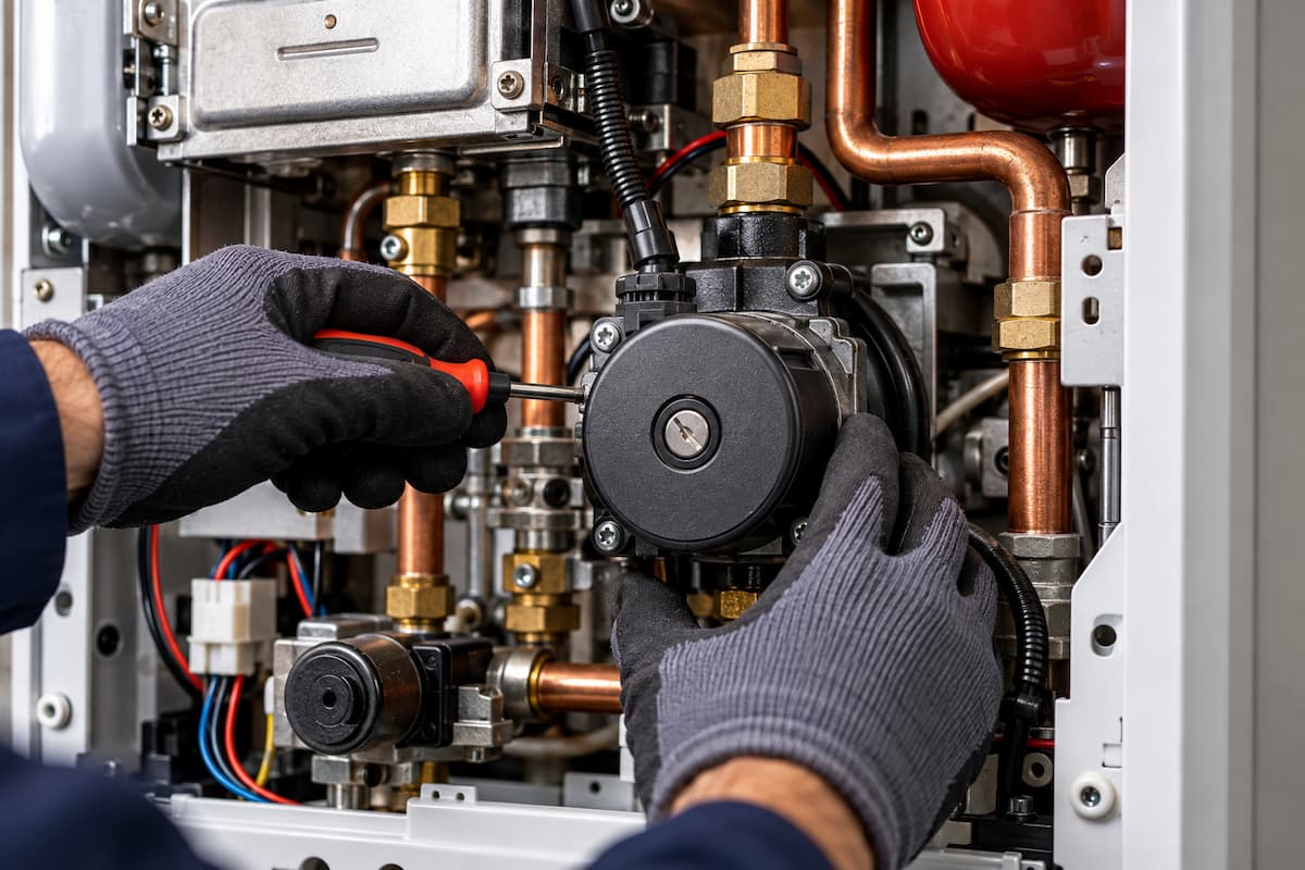
Modern boilers commonly incorporate integrated circulation pumps controlled by the appliance PCB, although some installations use external pumps or additional circulation arrangements.
Circulation Pump Types
Different pump designs and control arrangements can affect diagnostics.
Fixed Speed Pumps
Older heating installations may use pumps with selectable fixed operating speeds. The pump operates at the selected speed when energised, and the resulting flow is determined by the heating circuit’s resistance.
Increasing pump speed can alter the available head and flow, but it does not correct blocked filters, closed valves or other hydraulic restrictions.
Variable Speed Pumps
Variable speed pumps adjust their operation according to the selected control mode and system requirements.
Depending on the design, available modes may include:
- constant differential pressure
- proportional differential pressure
- fixed speed settings
- automatic operating modes
- external speed control
The right setting depends on the heating system and the manufacturer’s instructions. An unsuitable control mode can affect circulation, particularly where several heating circuits or motorised valves are involved.
Electronically Controlled Boiler Pumps
Many modern boilers use electronically commutated pumps, commonly known as ECM pumps. These provide efficient motor operation and may allow the PCB to adjust circulation in response to burner output, heating demand or appliance temperature.
Pump speed may therefore change during normal operation without indicating a fault. Engineers should identify the expected operating behaviour before interpreting changes in pump speed as abnormal.
Pump Electrical Operation and Control
Before diagnosing an electrical pump fault, engineers should identify the pump’s supply and control arrangement using the appliance wiring diagram.
Depending on the boiler, the pump may use:
- permanent mains supply
- switched mains supply
- separate electronic control signal
- speed or operating feedback
- integrated motor electronics
Some pumps receive a continuous mains supply while a separate signal controls operating speed. The presence of 230 V therefore does not necessarily prove that the pump has received the correct operating command.
Effective boiler electrical fault finding requires engineers to distinguish between supply voltage, control signals and feedback information. Measurements should follow the manufacturer’s procedures, particularly when low-voltage electronic circuits are involved.
Pump Control Signals
Some electronically controlled pumps use pulse width modulation (PWM) or another electronic control arrangement.
PWM lets the control system influence pump operation by varying a pulse signal’s characteristics. The relationship between the signal and pump speed depends on the specific pump design.
Manufacturer information should identify:
- electrical supply requirements
- control signal type
- connector functions
- expected operating behaviour
- feedback arrangements
- appropriate testing procedures
Engineers should not assume that a missing control signal produces the same result on every pump model. Incorrect testing can damage electronic pump controls or the boiler PCB.
Pump Speed Feedback
Where feedback is provided, the PCB may receive information about pump speed or operating status.
A feedback fault does not automatically prove that the pump has stopped rotating. The motor may operate while the feedback circuit fails to communicate correctly with the control system.
The engineer should compare physical pump operation with the information the PCB receives before identifying the defective component.
Diagnosing Pump Electrical Faults
Electrical diagnosis begins by confirming the pump has received the correct supply and command.
Pump Supply Present But No Operation
Where the correct electrical supply and operating command are confirmed but the pump remains stationary, possible causes include:
- failed pump motor
- defective electronic control
- seized rotor
- damaged electrical connection
- internal pump fault
The engineer should establish whether the pump is mechanically restricted or electrically defective before selecting a replacement.
Pump Supply Absent
If the expected supply is missing, the pump may be fully serviceable. Investigation should focus on the wiring, PCB output, relay, or control condition responsible for pump operation.
Do not interpret a missing supply as a PCB fault until you have checked the relevant inputs, connections, and manufacturer-specified operating conditions.
Pump Rotating But Circulation Inadequate
A rotating pump does not prove that sufficient water is moving through the heating circuit.
Possible causes include internal impeller damage, trapped air, hydraulic restrictions or unsuitable operating conditions. At this stage, the investigation should move from electrical operation towards hydraulic performance.
Pump Head and Flow Rate
A circulation pump must overcome the resistance created by the heating system.
Pump head is commonly expressed in metres and represents the differential pressure the pump can generate. Flow rate describes the quantity of water moving through the circuit over a given period.
The manufacturer’s pump performance curve represents the relationship between pump head and flow.
As system resistance increases, the operating point generally shifts toward a lower flow rate on a given pump curve.
For example, a pump that provides adequate circulation through a clean heating system may deliver much less flow when a filter becomes blocked, or a valve is partially closed.
Increasing pump speed may alter the operating point, but the underlying restriction still requires investigation.
Heat Transfer and Circulation
The relationship between heat output, water flow and temperature difference provides a useful diagnostic tool.
For water circulating through a heating system:
Q = ṁ × cp × ΔT
Where:
- Q = heat transfer rate in kW
- ṁ = mass flow rate in kg/s
- cp = specific heat capacity of water, approximately 4.18 kJ/kg·K
- ΔT = temperature difference in °C or K
For practical calculations using volumetric flow, the relationship can be approximated as:
Q = 1.16 × F × ΔT
Where:
- Q = heat transfer rate in kW
- F = water flow rate in m³/h
- ΔT = temperature difference in °C
The factor 1.16 approximates water under typical heating conditions. Antifreeze mixtures and different operating temperatures require appropriate fluid properties.
The equation demonstrates that transferring the same amount of heat across a smaller temperature difference requires a higher water flow rate.
Worked Flow Rate Calculation
Consider a boiler transferring 24 kW of heat into a heating circuit.
If the design temperature difference is 20°C:
F = 24 ÷ (1.16 × 20)
F ≈ 1.03 m³/h
This corresponds to approximately 17.2 litres per minute.
Now consider the same heat transfer with a temperature difference of 10°C:
F = 24 ÷ (1.16 × 10)
F ≈ 2.07 m³/h
This corresponds to approximately 34.5 litres per minute.
The calculation illustrates that halving the temperature difference requires approximately twice the water flow to transfer the same heat output.
These are theoretical flow calculations, not universal commissioning targets. Actual flow requirements depend on boiler design, burner output, system characteristics and manufacturer specifications.
Interpreting Flow and Return Temperatures
Comparing flow and return temperatures can help engineers assess heat transfer through the heating circuit.
The temperature difference is calculated as:
ΔT = Flow Temperature − Return Temperature
Suppose a boiler operates with a flow temperature of 75°C and a return temperature of 55°C.
ΔT = 75 − 55 = 20°C
The significance of this result depends on appliance design, operating conditions and burner output. A 20°C difference may suit one installation but be unsuitable for another.
Excessive Temperature Difference
A large flow and return temperature difference can indicate inadequate circulation, particularly where the boiler is operating at a significant heat output.
Potential causes include:
- insufficient pump performance
- incorrect pump speed
- restricted pipework
- blocked filters
- partially closed valves
- air within the circuit
- heat exchanger restrictions
The engineer should consider burner output and operating conditions before concluding that circulation is inadequate.
Small Temperature Difference
A small temperature difference does not automatically indicate excessive circulation.
It may occur because the burner is operating at reduced output, the heating system is approaching its target temperature, or the appliance is in a particular control stage.
Therefore, interpret temperature readings alongside burner modulation and pump operation.
Rapid Flow Temperature Increase
A boiler may ignite normally before the flow temperature rises rapidly and the burner shuts down.
If the flow pipe genuinely becomes very hot while the return remains relatively cool, inadequate circulation may be responsible.
However, inaccurate boiler sensors and thermistors can produce misleading temperature information. Engineers should compare displayed values with actual physical temperatures before investigating the hydraulic system or replacing a sensor.
Boiler Overheating and Pump Overrun
Insufficient circulation can cause heat to build up in the primary heat exchanger.
Depending on appliance design, this may cause rapid temperature increases, burner modulation, burner shutdown, overheat protection, or appliance lockout.
An overheat fault does not necessarily indicate a defective temperature sensor or safety device. The operation of gas safety devices must be considered alongside circulation and temperature control, as the appliance may be responding correctly to an unsafe operating condition.
Pump Overrun
Many boilers continue circulating water after the burner has stopped. This is known as pump overrun and helps remove residual heat from the heat exchanger.
The required overrun duration and operating conditions depend on the manufacturer.
If the pump stops when it should continue operating, residual heat may cause the appliance temperature to rise excessively.
Diagnosis should determine whether the pump receives the expected overrun command and whether circulation continues sufficiently after burner shutdown.
If the command is absent, investigate the electrical control circuit. If the pump operates but heat transfer is ineffective, focus should shift to hydraulic conditions.
Air Within The Heating Circuit
Air can interfere with circulation and reduce effective heat transfer.
Possible symptoms include:
- noisy pump operation
- gurgling pipework
- uneven radiator heating
- fluctuating temperatures
- reduced circulation
- repeated boiler shutdowns
Air may remain within a system following filling, draining or maintenance work. It may also indicate an underlying installation problem that allows air to enter or accumulate.
The engineer should assess system pressure, venting arrangements, and relevant hydraulic components before concluding the pump is defective.
Pump Cavitation
Cavitation occurs when local pressure conditions cause vapour bubbles to form within the liquid and subsequently collapse.
It can produce noise, vibration and damage to pump components.
Potential contributing factors include inadequate inlet pressure, excessive water temperature relative to local pressure and unsuitable hydraulic conditions.
Air within the system can produce similar symptoms, but air entrainment and cavitation are different problems.
Diagnosis should establish the physical conditions affecting the pump rather than relying on noise alone.
Hydraulic Restrictions and System Contamination
A circulation pump may operate correctly while resistance within the heating circuit prevents adequate water flow.
Restrictions can develop gradually through contamination or appear following maintenance, valve operation or component failure.
Blocked Filters and Strainers
Magnetic filters, mesh strainers and boiler inlet filters collect debris to protect heating components.
As material accumulates, resistance can increase, and circulation may become restricted.
A partially blocked filter may allow adequate flow at lower demand while contributing to overheating when the boiler operates at higher output.
Inspect and service filters and strainers according to their instructions and the installation arrangement.
Sludge and System Contamination
Magnetite and other debris may accumulate within radiators, pipework, pumps, valves and heat exchangers.
The resulting restrictions can reduce circulation and affect heat transfer.
If the engineer identifies significant contamination, they should assess the wider system rather than replace an affected component without addressing the underlying condition.
Heat Exchanger Restrictions
A restricted heat exchanger can produce symptoms similar to pump failure.
The pump may operate normally, but inadequate water flow through the heat exchanger can cause rapid temperature increases and burner shutdowns.
Diagnosis should consider pump performance, temperature behaviour and evidence of contamination before determining the appropriate repair.
Closed Valves and Restricted Circuits
Closed or incorrectly positioned valves can also restrict circulation.
Relevant components may include:
- boiler isolation valves
- zone valves
- motorised valves
- radiator valves
- balancing valves
A boiler that operates correctly in one heating mode but overheats in another may have a restriction associated with a particular hydraulic route.
Automatic Bypass Valves
Some heating systems incorporate an automatic bypass valve to maintain an appropriate circulation path when other valves close.
As differential pressure changes, the bypass may open to allow water to circulate through an alternative route.
An incorrectly adjusted or defective bypass arrangement can influence flow and temperature behaviour.
The engineer should assess the bypass against the boiler manufacturer’s minimum flow requirements and the hydraulic design.
Do not adjust a bypass valve to conceal an unresolved circulation problem.
Differential Pressure and Pump Performance
Differential pressure is the pressure difference generated across the pump.
It is related to pump head by:
Δp = ρ × g × H
Where:
- Δp = differential pressure in Pa
- ρ = fluid density in kg/m³
- g = gravitational acceleration, approximately 9.81 m/s²
- H = pump head in metres
For water, a pump head of approximately 5 metres corresponds to a differential pressure of around 49 kPa, or 0.49 bar.
This describes the pressure difference the pump generates, not the static pressure within the heating system.
Static Pressure Versus Circulation
Static system pressure and pump differential pressure represent different hydraulic conditions.
Static pressure indicates the pressure within the filled system, while pump differential pressure provides the driving force needed to circulate water through the circuit.
A boiler displaying 1.5 bar of static system pressure does not prove adequate circulation.
A pump may be stationary, restricted, or operating against excessive system resistance while the pressure gauge still shows a satisfactory reading.
Engineers should therefore avoid using static pressure alone as evidence of pump performance.
System pressure behaviour can also be influenced by expansion vessels, which accommodate the increase in water volume as the heating system warms. A defective or incorrectly charged vessel may cause pressure fluctuations, but this should be distinguished from the differential pressure generated by the circulation pump.
Hydraulic Balancing
Uneven radiator temperatures can result from poor water distribution between heating circuits.
Water tends to follow paths with lower hydraulic resistance, which can leave some radiators receiving insufficient flow.
Correct hydraulic balancing helps distribute water according to the system design.
Correct hydraulic balancing helps distribute water according to the system design. Although gas boilers and heat pumps may operate at different temperatures, the underlying relationship between flow rate, resistance and heat transfer remains relevant to both technologies.
Circulation Fault Diagnosis Table
| Reported Symptom | Possible Cause | Diagnostic Direction |
|---|---|---|
| Pump does not operate | Electrical supply, motor or control fault | Check supply, command, wiring and pump condition |
| Pump runs but boiler overheats | Restricted circulation or insufficient flow | Check valves, filters, hydraulic resistance and temperatures |
| Rapid flow temperature rise | Low circulation or inaccurate sensor | Compare actual and displayed temperatures |
| Large flow and return temperature difference | Insufficient flow relative to heat transfer | Assess pump performance and system restrictions |
| Pump noisy | Air, cavitation or mechanical defect | Assess system conditions and pump operation |
| Some radiators remain cold | Balancing, valve or circulation problem | Check affected circuits and valve operation |
| Overheat after burner shutdown | Pump overrun or circulation problem | Check overrun command and residual heat transfer |
| Pump feedback fault | Motor, electronics, signal or wiring problem | Compare physical operation with electronic feedback |
Pump and Circulation Fault Scenarios
The following scenarios demonstrate the importance of separating electrical operation, hydraulic performance and appliance control conditions.
Scenario One: Pump Does Not Start
A boiler receives a central heating demand, but the circulation pump remains stationary.
The engineer checks whether the appliance is commanding the pump to operate.
If the expected electrical supply or control signal is absent, the investigation moves to the wiring, PCB output, or conditions that prevent pump operation.
If the correct supply and command are present, the pump motor, electronics and mechanical condition become the primary diagnostic areas.
Do not replace the pump until the required operating conditions have been established.
Scenario Two: Pump Runs But Boiler Overheats
A boiler ignites normally, and the circulation pump operates. Shortly afterwards, the flow temperature rises rapidly, and the burner shuts down.
The engineer confirms that the flow pipe becomes very hot while the return remains considerably cooler.
This suggests inadequate heat transfer through the heating circuit.
Investigation may include pump performance, valve positions, filters, trapped air and heat exchanger restrictions. The pump running does not prove adequate circulation.
Scenario Three: Overheating After Burner Shutdown
A boiler operates normally during heating demand but records an overheat fault shortly after the burner stops.
Manufacturer information confirms that the pump should continue running during this period.
If the pump stops despite an expected operating command, electrical or pump diagnosis is appropriate.
If the pump continues operating but the temperature rises excessively, the engineer should assess the hydraulic conditions preventing residual heat transfer.
Scenario Four: Pump Runs But Radiators Remain Cold
A boiler and circulation pump operate normally, but several radiators receive little heat.
The engineer establishes whether the problem affects the entire heating system or particular circuits.
If some radiators heat correctly, the investigation may focus on balancing, radiator valves, trapped air, or localised restrictions.
Replacing the boiler pump may not resolve a problem caused by uneven water distribution.
Scenario Five: Intermittent Circulation Fault
A boiler operates normally when cold but begins shutting down after extended heating.
The engineer confirms that the flow temperature rises rapidly shortly before shutdown.
Possible causes include temperature-affected pump electronics, intermittent wiring faults, motor problems, or hydraulic restrictions.
Where safe and permitted by manufacturer procedures, take measurements under conditions that reproduce the fault rather than relying solely on readings taken when the appliance is cold.
Scenario Six: Circulation Problems Across Heating Zones
A property has several heating zones controlled by motorised valves.
The boiler operates normally when one zone calls for heat but overheats when another is selected.
This suggests the fault may be in the hydraulic route serving the affected zone.
Investigation may include valve operation, pipework restrictions, balancing and bypass arrangements.
The difference between operating modes provides evidence that can narrow the diagnostic area before components are replaced.
Pump Fault Codes and Diagnostic Data
Modern boilers may generate fault codes related to pump operation, circulation, excessive flow temperature, temperature difference, or overheat protection.
The code identifies the condition the control system detects, but it does not necessarily identify the failed component.
A circulation fault may originate from:
- pump motor or electronic control
- PCB output
- wiring
- hydraulic restriction
- trapped air
- incorrect valve operation
- inaccurate temperature information
Where available, service data can help engineers compare pump commands, operating status, temperatures and fault history.
Consider these readings alongside physical measurements and manufacturer specifications.
Pump and Circulation Diagnostic Workflow
A structured approach works for most circulation complaints.
Confirm customer-reported symptoms
↓
Check appliance fault history
↓
Establish heating demand and operating mode
↓
Confirm pump command and operation
↓
Pump operating?
If no:
↓
Investigate supply, control, wiring, motor and mechanical condition
If yes:
↓
Assess circulation and heat transfer
↓
Compare actual flow and return temperatures
↓
Check system valves, filters and restrictions
↓
Assess pump performance and hydraulic conditions
↓
Confirm temperature sensor accuracy
↓
Identify and correct the cause
↓
Verify appliance operation and safety
The objective is to determine whether the problem originates in the pump, its control system, or the hydraulic circuit, rather than relying on the reported symptom alone.
Repair and Recommissioning
After correcting a circulation fault, the engineer should verify that the repair has resolved the original problem.
Depending on the work completed, checks may include:
- pump electrical connections
- pump operation and control mode
- system pressure
- air removal
- flow and return temperatures
- heating circuit operation
- valve operation
- pump overrun
- boiler temperature control
- safety controls
- combustion performance where required
Where repairs or manufacturer procedures require combustion verification, combustion analysis and flue gas testing must be carried out using the appropriate equipment and appliance requirements. Correct circulation should also be confirmed across the relevant operating modes before returning the boiler to service.
ACS Assessment Considerations
Diagnosing pump and circulation faults requires engineers to combine appliance operation, electrical testing, and hydraulic principles.
Candidates should recognise that a pump fault code does not automatically identify a defective pump. The engineer must establish whether the pump receives the correct command, operates, and provides adequate circulation.
The same principle applies to boiler overheating. An overheat device may be functioning correctly while restricted water movement causes the appliance temperature to rise.
A structured diagnostic approach separates the reported condition from its underlying cause using appropriate measurements and manufacturer information.
Pump and Circulation Inspection Checklist
| Diagnostic Stage | Completed |
|---|---|
| Customer reported symptoms confirmed | ☐ |
| Manufacturer information consulted | ☐ |
| Fault history checked | ☐ |
| Heating demand confirmed | ☐ |
| Pump type identified | ☐ |
| Pump electrical supply checked where required | ☐ |
| Pump control command checked where required | ☐ |
| Pump operation confirmed | ☐ |
| System pressure verified | ☐ |
| Flow and return temperatures assessed | ☐ |
| Temperature sensor accuracy considered | ☐ |
| Isolation and zone valves checked | ☐ |
| Filters and strainers assessed | ☐ |
| Air and circulation restrictions investigated | ☐ |
| Pump overrun checked where applicable | ☐ |
| Cause established before replacement | ☐ |
| Repair completed | ☐ |
| Appliance operation verified | ☐ |
| Relevant safety checks completed | ☐ |
Gas Training Courses In Staffordshire
Pump and circulation diagnosis is an important part of domestic boiler fault finding. Engineers need to combine electrical testing with knowledge of hydraulic systems, temperature control and appliance operation to distinguish a failed component from an installation problem.
Staffordshire Training Services provides accredited gas training in Stafford for new entrants and experienced engineers developing their technical competence. Practical training at our Stafford centre helps candidates apply engineering principles to realistic appliance and installation scenarios.
The Gas Managed Learning Programme provides a structured route into domestic gas engineering, combining technical knowledge with practical experience and progression towards ACS assessment.
Engineers carrying out electrical diagnosis on pumps, sensors and boiler control circuits also need appropriate isolation procedures. The Safe Isolation of Electrical Installations Course supports the electrical safety skills required before testing and working on appliance circuits.
Related Articles
- Boiler Electrical Fault Finding For Gas Engineers
- Boiler Sensors and Thermistors For Gas Engineers
- Heat Pump Circulation Pumps and Flow Rates
- Emergency Control Valve Testing and Meter Installation Safety
- Gas Safety Devices and Flame Supervision Systems For Gas Engineers
Prefer an AI Summary?