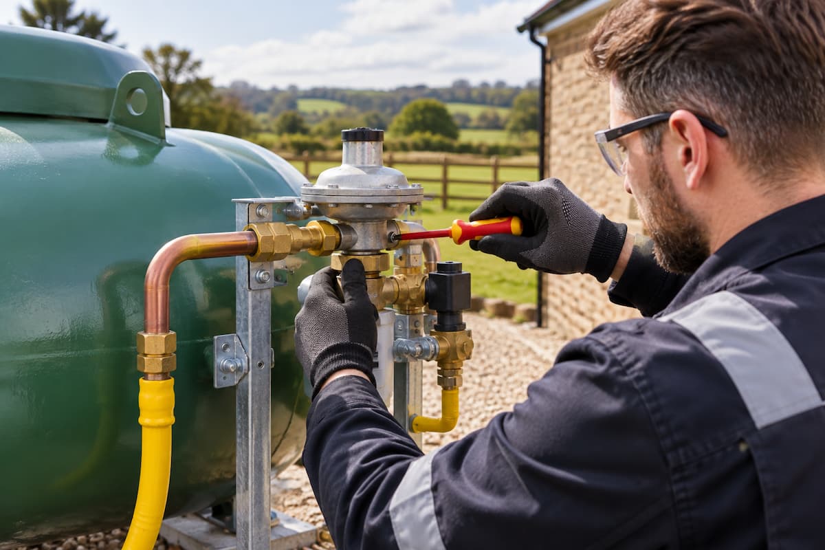
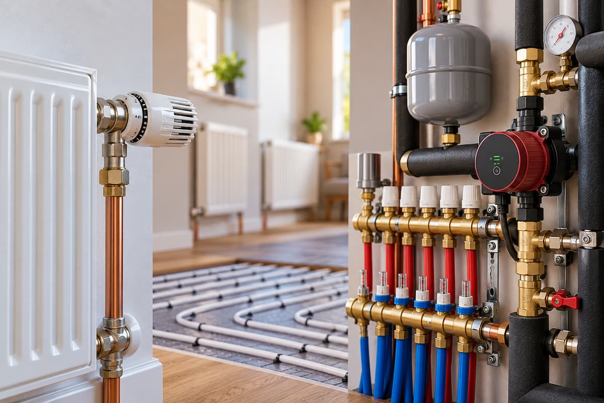
A heat pump can have the correct design flow rate and a correctly selected circulation pump, yet still deliver disappointing heating performance if that flow is distributed poorly around the property.
Hydraulic balancing is the process of controlling water distribution so that each part of the heating system receives the flow it needs. In a radiator system, this means preventing emitters close to the circulation pump from taking a disproportionate share of the available flow. In an underfloor heating system, individual loops need to be adjusted according to their design requirements.
Balancing becomes particularly important with heat pumps because these systems depend on controlled water flow, low operating temperatures and correctly sized emitters working together. Increasing the heat pump flow temperature can sometimes mask poor distribution, but it does not correct the underlying hydraulic problem.
For renewable installers, effective balancing therefore forms an important part of heat pump commissioning and system optimisation.
System Flow and Emitter Flow
The total flow through a heat pump system and the flow through individual emitters are related, but they represent different parts of the hydraulic design.
A heat pump might require 24 litres per minute through its primary circuit. That does not mean every radiator receives the same flow.
Instead, the available water is distributed across the operating emitters according to their heating requirements and the resistance of each flow path.
A simplified four radiator circuit might look like this:
┌────► RADIATOR 1 ────┐
│ │
HEAT PUMP ───► PUMP ───┼────► RADIATOR 2 ────┤
│ │
├────► RADIATOR 3 ────┤──► RETURN
│ │
└────► RADIATOR 4 ────┘
Without balancing, water does not automatically divide according to the heat requirement of each room. It follows the available hydraulic paths.
Shorter or less restrictive circuits can therefore receive more flow than longer or more resistant circuits.
Poorly Balanced Heating Circuits
Consider four radiators connected to the same distribution circuit.
The radiator nearest the pump has a relatively short hydraulic path, while the final radiator has a longer path containing additional pipework and fittings.
Without suitable balancing, the distribution could behave approximately like this:
HEAT PUMP
│
▼
CIRCULATION PUMP
│
├────────► RADIATOR 1 HIGH FLOW
│
├────────► RADIATOR 2 GOOD FLOW
│
├────────► RADIATOR 3 REDUCED FLOW
│
└────────► RADIATOR 4 LOW FLOW
The first radiator may heat rapidly while the final radiator struggles to reach its intended output.
Turning up the circulation pump may increase total system flow, but it does not necessarily correct the distribution problem. The first radiator may receive even more water.
Balancing introduces additional resistance into the easier flow paths so that sufficient flow remains available for the more resistant circuits.
Balanced Flow Distribution
After adjustment, the system should distribute water more closely to each emitter’s requirements.
HEAT PUMP
│
▼
CIRCULATION PUMP
│
├────────► RADIATOR 1 DESIGN FLOW
│
├────────► RADIATOR 2 DESIGN FLOW
│
├────────► RADIATOR 3 DESIGN FLOW
│
└────────► RADIATOR 4 DESIGN FLOW
Design flow does not necessarily mean identical flow through every radiator.
A large radiator serving a room with a higher calculated heat loss may require more water than a small radiator in a room with a much lower heating requirement.
Effective hydraulic balancing therefore aims for the appropriate flow through each emitter, rather than equal flow everywhere.
Heat Loss and Hydraulic Balancing
Room by room heat loss calculations provide the foundation for emitter selection and hydraulic design.
If one room requires 1.5kW at design conditions and another requires only 500W, their heating requirements differ substantially. The emitter sizes and associated flow requirements should reflect this.
Accurate heat loss calculations for renewable systems therefore provide useful information when establishing emitter duties.
Hydraulic balancing cannot compensate for an incorrectly sized radiator. If an emitter cannot provide the required heat output at the intended water temperatures, increasing its flow indefinitely will not transform it into a correctly sized emitter.
This distinction is important during fault diagnosis.
Poor room temperature could result from insufficient flow, an undersized emitter, excessive heat loss, incorrect controls or a combination of factors.
Radiator Flow Requirements
The required flow through an individual radiator depends on the amount of heat being transferred and the temperature difference across the emitter.
The same basic heat transfer relationship used for total heat pump flow can also be applied at emitter level.
For water:
Flow rate in litres per second = heat output in kW ÷ (4.18 × ΔT)
Consider a radiator required to deliver 1.2kW with a 5°C temperature difference between its inlet and outlet.
1.2 ÷ (4.18 × 5) = approximately 0.057 litres per second
Converted to litres per minute:
0.057 × 60 = approximately 3.4 litres per minute
This gives the installer an approximate design flow for that emitter.
A smaller radiator delivering 600W under the same conditions would require approximately half that flow.
The calculations illustrate why simply setting every lockshield valve to the same position is not hydraulic balancing.
Radiator Output at Low Temperatures
Radiators connected to heat pumps usually operate at lower water temperatures than emitters on many traditional boiler systems.
Their output therefore needs to be assessed at the intended heat pump operating temperatures.
The principles covered in radiator sizing for heat pumps are directly relevant to balancing because the installer first needs to establish that each emitter is capable of meeting the room load.
Once the emitter has been correctly selected, hydraulic balancing helps ensure it receives the flow needed to achieve its intended performance.
Lockshield Valves
On a conventional radiator circuit, the lockshield valve provides a means of introducing resistance into individual radiator branches.
Radiators with easier hydraulic paths may require greater restriction. More distant or resistant emitters may require less.
The aim is not to close valves unnecessarily. It is to establish controlled water distribution throughout the system.
Small valve adjustments can have a significant effect because valve resistance does not change in a simple linear relationship with handle position.
For this reason, randomly opening every lockshield valve by the same number of turns is unlikely to produce an accurately balanced system.
Temperature Difference Across Radiators
Flow and return temperatures can provide useful information during balancing.
Measurements can be taken at the inlet and outlet of an emitter once the heating system has reached reasonably stable operating conditions.
FLOW
│
40°C
│
▼
┌───────────┐
│ RADIATOR │
└───────────┘
│
▼
35°C
│
RETURN
ΔT = 5°C
If the temperature difference is significantly larger than expected, insufficient water flow may be one possible cause.
A very small temperature difference may indicate relatively high flow through the radiator, although heat demand, radiator output and current heat pump operating conditions must also be considered.
Temperature measurements should therefore support balancing rather than becoming the only measurement used to determine valve settings.
Heat Pump ΔT and Radiator ΔT
The temperature difference measured across the heat pump should not automatically be assumed to be identical across every individual radiator.
System configuration, mixing, hydraulic separation, varying emitter duties and operating conditions can all influence local measurements.
This becomes particularly important on larger or mixed systems.
An installer might measure an acceptable ΔT across the heat pump while still finding individual branches that are poorly balanced.
Whole system measurements and emitter measurements therefore provide different diagnostic information.
Circulation Pumps and Balancing
Hydraulic balancing and circulation pump selection are closely connected.
The pump establishes the pressure differential that drives water through the heating circuit. The balancing devices determine how that flow is distributed between the available paths.
If the pump cannot provide the required system duty, balancing alone cannot create sufficient flow.
Conversely, fitting or setting a larger pump cannot correct poor distribution between circuits.
The relationship between pump duty, head, system resistance and ΔT is covered in Heat Pump Circulation Pumps and Flow Rates. Together, circulation pump commissioning and hydraulic balancing establish both the quantity of water moving through the system and its distribution.
Variable Speed Pumps
Variable speed circulation pumps can adjust their operation as hydraulic resistance changes.
Depending on the equipment and application, control modes can include fixed speed, constant pressure or proportional pressure operation.
This interaction needs to be considered during balancing.
Restricting one branch alters system resistance. Thermostatic valves closing during normal operation can change it again. The circulation pump may then adjust its output according to its selected control mode.
The final system should therefore be assessed under realistic operating conditions rather than balanced solely according to conditions that rarely occur once the property is occupied.
Thermostatic Radiator Valves
Thermostatic radiator valves add another variable to the hydraulic system.
As rooms approach their temperature targets, TRVs can reduce or stop water flow through individual radiators.
The total resistance of the heating system then changes.
Consider a simplified system with four radiators:
ALL TRVs OPEN
PUMP ───► R1
├──► R2
├──► R3
└──► R4
TWO TRVs CLOSED
PUMP ───► R1
│
X R2 CLOSED
│
├──► R3
│
X R4 CLOSED
The same pump is now supplying fewer open hydraulic paths.
The system design and pump controls need to accommodate these changing conditions without creating excessive differential pressure or allowing heat pump flow to fall below acceptable levels.
Minimum Heat Pump Flow
Balancing should never be considered without reference to the heat pump manufacturer’s minimum flow requirement.
Closing multiple zones, actuators, or TRVs can reduce the available water path through a direct heat pump circuit.
If flow through the heat pump drops below its permitted minimum, operation may become unstable, or the unit may generate a flow fault.
This is one reason the distinction between total heat pump flow and individual emitter flow is important.
The objective is to balance the heating distribution while maintaining the hydraulic conditions required by the heat pump.
Bypass Arrangements
Some heating systems use an automatic bypass valve or another hydraulic arrangement to maintain a water path as control valves close.
Where a bypass is installed, its setting matters.
A bypass that opens too readily can allow water to take an easier route back towards the heat pump rather than travelling through the heating circuit.
This can reduce useful heat distribution and alter flow and return temperatures.
A bypass that does not provide the intended function when required can create a different set of hydraulic problems.
Its selection and setting should therefore follow the system design and manufacturer requirements rather than being treated as a universal solution to flow problems.
Hydraulic Separation
Systems incorporating hydraulic separation require balancing on both sides of the hydraulic arrangement.
The primary circuit must provide the heat pump with its required flow, while the secondary circuit must distribute water correctly to the emitters.
PRIMARY CIRCUIT SECONDARY CIRCUIT
HEAT PUMP RADIATORS
│ ▲
▼ │
PRIMARY ─────► HYDRAULIC ─────► SECONDARY
PUMP SEPARATOR PUMP
▲ │
│ ▼
└────────── RETURN ◄──────────────┘
As covered in hydraulic separation in heat pump systems, significant differences between primary and secondary flow can cause mixing through the separator.
Balancing the secondary circuit therefore does not remove the need to check primary and secondary flow relationships.
Buffer Vessels and Balancing
A four-port buffer vessel can provide hydraulic separation between the heat pump and heating distribution system.
The secondary heating circuit still requires appropriate balancing.
The presence of a buffer does not ensure that each radiator or underfloor heating loop automatically receives the correct flow.
Likewise, altering secondary pump speed can change the relationship between primary and secondary flow through the vessel.
Where a buffer vessel forms part of the hydraulic design, installers should consider the complete system rather than treating the vessel as an isolated component.
Underfloor Heating Balancing
Underfloor heating manifolds provide a more visible method of distributing water between individual circuits.
Each loop can have a different length and heating requirement, so identical flow through every loop is not necessarily appropriate.
Manifold flow meters allow the installer to adjust individual circuit flow according to the system design.
UFH MANIFOLD
FLOW ───────────────┬──────────────
│
┌─────────┼─────────┐
│ │ │
▼ ▼ ▼
LOOP 1 LOOP 2 LOOP 3
1.5 L/m 2.0 L/m 1.0 L/m
│ │ │
└─────────┼─────────┘
│
RETURN ─────────────┴──────────────
The example shows that balanced flow does not necessarily mean equal flow.
A larger area or loop with a greater heating requirement may need a higher flow than a smaller circuit.
Underfloor Loop Length
Loop length influences hydraulic resistance.
A longer underfloor heating circuit generally presents greater resistance than a shorter circuit using the same pipe diameter.
Very long loops can therefore become difficult to balance against much shorter circuits.
This should ideally be addressed during system design rather than relying on manifold adjustment to correct unsuitable loop arrangements after installation.
Balancing valves and flow meters provide control, but they cannot remove excessive resistance from an incorrectly designed circuit.
Mixed Emitter Systems
Properties can contain both radiators and underfloor heating.
These circuits may have different hydraulic characteristics, flow requirements and control arrangements.
┌────► RADIATOR CIRCUIT
│
HEAT PUMP ─► HYDRAULIC ┤
SEPARATION │
└────► UFH MANIFOLD
The radiator circuit may contain TRVs and individual lockshield valves, while the underfloor circuit contains multiple manifold loops and actuators.
Each part requires its own balancing considerations.
The overall design must also maintain suitable flow through the heat pump while the demand from either distribution circuit changes.
Zoning and Changing Flow
Zoned heating can make hydraulic balancing more challenging because the active circuit configuration changes during operation.
For example, a property may have upstairs and downstairs zones.
With both zones open, total flow is distributed across the complete system. If the upstairs zone closes, the downstairs circuit receives the available pump pressure under a different hydraulic condition.
Systems with several small zones can experience even greater variation.
Installers therefore need to consider both design conditions and partial load operation when commissioning a heat pump system.
Differential Pressure
Water flows through a heating circuit because the circulation pump creates a pressure difference.
As valves close, the resistance presented by the remaining open circuits changes. Differential pressure across those circuits can therefore increase.
Possible indications include valve noise, excessive flow through open emitters or unstable control.
Correct pump settings, balancing and appropriate system design work together to manage these conditions.
Increasing pump speed to improve one poorly performing circuit may create excessive differential pressure elsewhere, which is another reason fault diagnosis should look at the complete hydraulic system.
Balancing and Weather Compensation
Hydraulic balancing supports effective weather compensated operation.
Weather compensation aims to provide the lowest suitable heating water temperature for the current outdoor conditions.
For this strategy to work effectively, the available heat needs to reach the rooms that require it.
If one part of the property is starved of flow, an installer or occupant may respond by increasing the heating curve to make that room warmer.
Other rooms may then receive more heat than necessary, while the heat pump operates at a higher flow temperature.
Correcting the hydraulic imbalance lets you set the heating curve to the building’s actual requirements rather than compensating for poor water distribution.
Balancing and Heat Pump Efficiency
Poor hydraulic balance can affect heat pump efficiency indirectly in several ways.
A cold room may encourage higher flow temperature settings. Excessive pump speeds can increase auxiliary electricity consumption. High flow through some emitters can coexist with inadequate flow elsewhere, while unstable zoning can alter heat pump operating conditions.
A balanced system provides a stronger foundation for lower operating temperatures and controlled heat distribution.
This is particularly important for low temperature heating systems, where emitter sizing, water temperature and flow need to work together.
Balancing Sequence
Hydraulic balancing should be approached methodically.
Before making valve adjustments, the installer should confirm that the system is capable of operating correctly.
Initial checks should include:
- Correct system pressure
- Clean filters and strainers
- Fully vented circuits
- Correct valve positions
- Suitable circulation pump setting
- Required heat pump flow
- Correct control operation
- Suitable emitter sizing
- Available design information
Balancing a circuit with air, a blocked filter, or an incorrectly configured pump can lead to misleading results.
Once the system is operating correctly, individual branches and emitters can be adjusted according to the chosen balancing method and design information.
Practical Radiator Balancing Sequence
A practical sequence might involve bringing the heating system into stable operation, opening the required circuits and establishing that the heat pump and circulation pump are providing the intended flow.
Individual radiator temperatures and flow conditions can then be assessed.
Emitters receiving excessive flow can be progressively restricted while ensuring more resistant circuits receive sufficient water.
Adjustments should be given time to influence system temperatures before further changes are made.
The process should continue until flow distribution is consistent with the intended emitter duties and the system remains hydraulically stable.
Balancing is therefore an iterative commissioning process rather than a single valve adjustment.
Measuring Temperatures Correctly
Temperature measurements should be taken consistently.
If surface probes are used on pipework, good thermal contact is important. Measurements should be taken at comparable positions, and the system should be allowed to reach sufficiently stable operation.
Installers should also recognise that heat pumps modulate.
Flow temperature, return temperature and compressor output can all change while measurements are being taken.
A reading taken immediately after a heating cycle starts may therefore differ significantly from one taken after the system has been operating steadily.
Balancing Fault Symptoms
Several symptoms can point towards poor hydraulic balance.
| Symptom | Possible Hydraulic Cause |
|---|---|
| Radiators near the pump heat rapidly | Excessive flow through easier hydraulic paths |
| Distant radiators remain cooler | Insufficient flow through higher resistance circuits |
| One room repeatedly fails to reach temperature | Flow restriction, poor balance, emitter sizing or control issue |
| Valve or pipework noise | Excessive differential pressure or water velocity |
| Large radiator ΔT | Potentially insufficient emitter flow |
| Very small radiator ΔT | Potentially excessive flow or low current heat transfer |
| Heat pump flow faults as zones close | Insufficient remaining water path or unsuitable hydraulic arrangement |
| UFH rooms heat unevenly | Incorrect manifold flow settings, circuit resistance or control issue |
These observations provide diagnostic clues rather than automatic conclusions.
The wider process covered in heat pump fault finding for renewable installers remains important because hydraulic symptoms can overlap with control, sensor, emitter and heat pump faults.
Balancing Example
Consider a property with four radiators serving rooms with different heating requirements.
The calculated emitter flows are:
| Radiator | Required Output | Approximate Design Flow At 5°C ΔT |
|---|---|---|
| Living Room | 1.5kW | 4.3 litres per minute |
| Kitchen | 1.0kW | 2.9 litres per minute |
| Bedroom | 0.8kW | 2.3 litres per minute |
| Hall | 0.5kW | 1.4 litres per minute |
The hall radiator is physically closest to the circulation pump and initially receives a disproportionately high flow. The living room radiator is at the end of a longer pipe run and heats slowly.
Increasing pump speed might increase total flow but would not address the underlying distribution.
Instead, the easier circuits are adjusted so that more of the available differential pressure can drive the required flow through the more resistant branches.
The final settings are verified through appropriate flow and temperature measurements rather than simply comparing how quickly each radiator feels warm.
Rebalancing After System Changes
Hydraulic balance can change after alterations to the heating system.
Examples include replacing radiators, adding an extension, installing additional underfloor heating, changing a circulation pump, altering zone controls or modifying pipework.
Even maintenance can affect hydraulic conditions if valves or pump settings are changed.
The system should therefore be reassessed where modifications materially alter flow paths or resistance.
Previous valve positions should not automatically be assumed to remain suitable after the hydraulic circuit has changed.
Commissioning Records
Balancing measurements and final settings should be recorded where practical.
| Item | Commissioning Record |
|---|---|
| Total heat pump flow | Record measured value |
| Circulation pump setting | Record final setting or control mode |
| Heat pump flow temperature | Record measured value |
| Heat pump return temperature | Record measured value |
| System ΔT | Record calculated value |
| Radiator valve settings | Record where appropriate |
| UFH loop flows | Record individual design and measured values |
| Zone operation | Record checks under relevant operating conditions |
These records provide useful baseline information if an engineer later returns to investigate reduced performance or uneven heating.
They also complement the wider checks required during heat pump commissioning.
Hydraulic Balancing as Part of System Design
Hydraulic balancing should not be viewed as an attempt to correct poor design after installation.
Successful heat pump systems begin with accurate heat loss calculations, appropriate emitter selection, suitable pipe sizing, adequate circulation pump duty and a hydraulic arrangement capable of operating across the expected range of heating demand.
Balancing then fine-tunes the distribution of water within that design.
A system with severely undersized pipework, unsuitable emitters or excessive circuit resistance cannot always be corrected through valve adjustment.
For engineers moving into renewable heating, this system approach is an important part of developing practical heat pump design and commissioning skills.
Heat Pump Training In Staffordshire
Hydraulic balancing brings together several important areas of renewable heating knowledge. Installers need to understand heat loss, emitter output, flow rates, circulation pumps, pressure loss, controls and commissioning rather than treating individual components separately.
Staffordshire Training Services provides heat pump training at its Stafford training centre for heating engineers developing practical skills in renewable systems.
The Air Source Heat Pump Systems Level 3 Focused Course supports engineers developing their knowledge of air source heat pump systems. In contrast, the Ground Source Heat Pump Systems Level 3 Focused Course provides focused training for ground source technology.
Engineers looking to develop skills across both technologies can take the Air and Ground Source Heat Pump Systems Level 3 Combined Course.
The Low Temperature Heating and Hot Water Systems Level 3 Course is particularly relevant to engineers developing their knowledge of heat loss, emitter selection, system temperatures and the design principles that support effective hydraulic balancing.
Correct balancing allows the heat generated by a heat pump to reach the parts of the property that require it. Combined with suitable system flow, correctly sized emitters, and accurate commissioning, it helps create a heating system that delivers comfort without relying on unnecessarily high operating temperatures.
Related Articles
- Volumisers In Heat Pump Systems
- Hydraulic Separation In Heat Pump Systems
- Heat Pump Circulation Pumps and Flow Rates
- Buffer Vessels in Heat Pump Systems
- Heat Pump Fault Finding For Renewable Installers
Prefer an AI Summary?