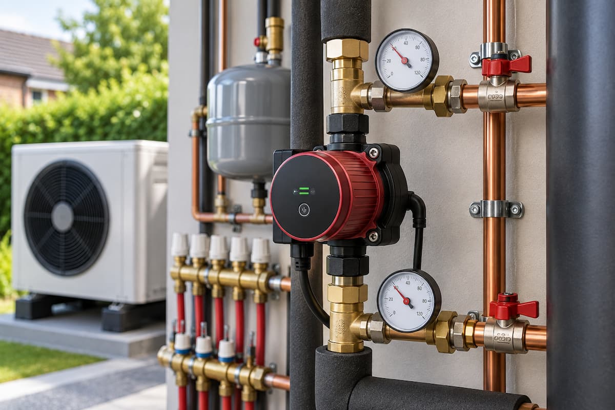
Heat pumps depend on water circulation to move thermal energy from the heat pump into radiators, underfloor heating and other emitters. If the required flow cannot be maintained, even a correctly sized heat pump can struggle to deliver its intended output.
For renewable installers, circulation pump selection is therefore about considerably more than moving water around a heating system. The pump must provide the required flow against the resistance created by pipework, fittings, valves, heat exchangers, and emitters.
Flow rate also needs to be considered alongside the temperature difference between flow and return water. Together, these values give installers valuable information about how much heat the system transfers.
This makes circulation pumps and flow rates central to heat pump design, commissioning and fault diagnosis.
Heat Pump Flow Rate
A heat pump transfers energy into the water passing through its heat exchanger. It must then transport that energy around the heating system.
The required water flow depends primarily on the heat output being transferred and the temperature difference between the flow and return. A smaller temperature difference requires more water to carry the same amount of heat.
This is particularly relevant to low temperature heating systems, where heat pumps typically operate with different hydraulic conditions from older boiler systems.
The manufacturer’s installation instructions should always provide the required operating flow range for the individual heat pump. This figure should form one of the starting points for pump selection and commissioning.
Minimum Flow and Design Flow
Several different flow figures may appear during the design and commissioning of a heat pump system, and they should not be treated as interchangeable.
Minimum flow rate is the lowest flow the manufacturer permits through the heat pump under specified operating conditions. Falling below this value can reduce heat transfer, trigger protective operation, or cause a flow fault.
Design flow rate is the calculated water flow required to transfer the intended heat output at the selected design temperature difference.
Actual operating flow is the flow measured while the completed heat pump system is running.
The manufacturer’s minimum flow should therefore not automatically be used as the design target.
For example, a heat pump may be capable of operating at its specified minimum flow. At the same time, the design conditions require a higher flow to transfer the calculated heat output at the intended ΔT.
During commissioning, the installer should know which value is being checked and compare the measured flow with the relevant manufacturer and system design requirements.
Flow and Return Temperature Difference
The difference between flow and return temperature is usually referred to as ΔT, or Delta T.
If water leaves the heat pump at 40°C and returns at 35°C, the temperature difference is 5°C.
HEAT PUMP
│
│ FLOW 40°C
▼
HEATING SYSTEM
│
│ RETURN 35°C
▼
ΔT = 5°C
This temperature difference provides useful information about the relationship between water flow and heat transfer.
A large ΔT may indicate that water is circulating too slowly for the heat being transferred. A very small ΔT may indicate a higher flow rate, although system demand, compressor modulation and operating conditions must also be considered before concluding.
Installers should therefore assess ΔT alongside measured flow rather than using temperature difference alone as a diagnostic measurement.
Calculating Required Flow
The relationship between heat output, water flow and temperature difference can be expressed using:
Heat output = mass flow rate × specific heat capacity × ΔT
For water, a useful approximation for heating calculations is:
Flow rate in litres per second = heat output in kW ÷ (4.18 × ΔT)
Consider an 8kW heat pump operating with a design ΔT of 5°C:
8 ÷ (4.18 × 5) = approximately 0.38 litres per second
Converting this to litres per minute:
0.38 × 60 = approximately 23 litres per minute
The heating circuit therefore needs to accommodate roughly 23 litres per minute at those operating conditions.
This calculation provides a useful design reference. Installers should still use the manufacturer’s specified operating requirements for the actual appliance and account for the heat transfer fluid being used.
Flow Rate at Different Temperature Differences
The effect of ΔT becomes clearer when you consider the same heat output at different temperature differences.
For an 8kW heat output:
| Design ΔT | Approximate Required Flow |
|---|---|
| 3°C | 38.3 litres per minute |
| 5°C | 23.0 litres per minute |
| 7°C | 16.4 litres per minute |
| 10°C | 11.5 litres per minute |
The heat output has not changed. The difference is the amount of water required to transport that heat.
This is one reason pipework and pump selection deserve careful attention when converting an existing heating system to a heat pump.
Circulation Pump Duty
A circulation pump must provide both the required flow rate and sufficient pressure to overcome resistance within the circuit.
Selecting a pump solely because its maximum advertised flow exceeds the calculated requirement is not enough.
The actual operating point depends on the interaction between the pump and the heating system’s hydraulic resistance.
Resistance can be created by:
- Pipe length
- Pipe diameter
- Bends and fittings
- Valves
- Heat exchangers
- Radiators
- Underfloor heating manifolds
- Filters and strainers
- Hydraulic components
As flow increases, resistance within the circuit also increases. The circulation pump therefore needs to achieve the required flow at the head created by the complete circuit.
Pump Head
Pump head is an important part of circulation pump selection, but the term can be confusing.
In a sealed heating system, pump head should not simply be interpreted as the vertical height between the circulation pump and the highest radiator.
The circulator is primarily overcoming the resistance to water movement created by the heating circuit.
Consider a system requiring:
Required flow: 24 litres per minute
Calculated circuit resistance: 3.5 metres head
Required pump duty: 24 litres per minute at approximately 3.5 metres head
The final part is important.
A pump may deliver more than 24 litres per minute under very low-resistance conditions but fail to deliver that flow once it operates against the resistance of the actual heating circuit.
Flow and head therefore need to be considered together.
Pump Curves
Manufacturers publish pump curves showing the relationship between flow rate and available pump head.
A simplified pump curve can be represented as:
PUMP
HEAD
▲
│\
│ \
│ \
│ \
│ \ Pump Curve
│ \
│ ● Operating Point
│ /
│ / System Resistance
│ /
│ /
└────────────────────────► FLOW RATE
The operating point occurs where the pump curve intersects the system resistance curve.
If system resistance changes, perhaps because valves close or a filter becomes restricted, the operating point also changes.
This means the flow measured in the completed installation can differ considerably from the pump’s theoretical maximum flow.
Understanding pump curves helps installers select circulation pumps according to actual system requirements rather than relying on maximum figures from a product specification.
Pipework and Flow Resistance
Pipe diameter significantly influences hydraulic resistance.
Pushing a high flow rate through restrictive pipework increases water velocity and pressure loss. The circulation pump then has to work harder to maintain the required flow.
This can contribute to noise, increased pumping energy and insufficient flow at the heat pump.
Existing pipework therefore needs careful assessment during retrofit installations. A property may have pipework that performed adequately with a boiler but is less suitable for the flow requirements of a replacement heat pump system.
Simply fitting a more powerful circulation pump is not necessarily the correct solution. The pipework itself may be restricting the achievable flow.
Water Velocity
Flow rate and pipe diameter together determine the water velocity through the pipework.
Increasing pump speed may increase flow, but it can also increase velocity and pressure loss through restrictive sections of the system.
Installers encountering hydraulic problems should therefore consider flow, velocity and pressure loss together.
| Observation | Installer Consideration |
|---|---|
| Required flow cannot be achieved | Check pipe diameter and circuit resistance before increasing pump speed |
| High pipe velocity | Review pipe sizing and required system flow |
| Valve or pipework noise | Check velocity, differential pressure and pump setting |
| Large pressure loss | Check restrictive pipework, fittings, valves and filters |
The objective is not simply to force the calculated volume of water through whatever pipework is present. The hydraulic circuit should be able to carry the required flow at an appropriate pump duty.
This reinforces the importance of considering hydraulic design alongside heat pump system design rather than treating pump selection as a separate task.
Glycol and Heat Transfer Fluid
Heat pump installations may contain a water and glycol mixture for frost protection, depending on the system arrangement and manufacturer requirements.
Adding glycol changes the physical properties of the circulating fluid compared with plain water.
The effects can include changes to:
- Specific heat capacity
- Viscosity
- Hydraulic resistance
- Heat transfer
- Required pump duty
- Flow calculations
As glycol concentration increases, the fluid can become more viscous. This can increase resistance through pipework and components and alter the duty required from the circulation pump.
The simple water flow calculation shown earlier should therefore not automatically be applied to every glycol system without adjustment.
Installers should use the heat pump manufacturer’s technical information and the data supplied for the specified heat transfer fluid and concentration.
This is especially important when checking pump suitability and commissioning flow rates because calculations based solely on water properties may not accurately represent the completed system.
Primary Heat Pump Circulation
In a direct system, one circulation pump may move water through both the heat pump and heating distribution circuit.
A simplified arrangement is:
┌───────────┐
│ HEAT PUMP │
└─────┬─────┘
│
▼
┌─────────────┐
│ CIRCULATION │
│ PUMP │
└─────┬───────┘
│
▼
┌─────────────┐
│ RADIATORS / │
│ UFH │
└─────┬───────┘
│
└──────────────► HEAT PUMP RETURN
This arrangement can reduce the number of pumps and associated electrical consumption where the hydraulic design permits it.
The circulation pump must still provide sufficient flow through the entire circuit under the range of operating conditions the system will encounter.
Pumps and Hydraulic Separation
More complex systems may use separate primary and secondary circulation pumps.
The primary pump maintains the required flow through the heat pump, while the secondary pump supplies the heating distribution circuit.
PRIMARY CIRCUIT SECONDARY CIRCUIT
┌───────────┐ ┌──────────────┐
│ HEAT PUMP │──────►┌─────────┐────►│ RADIATORS / │
└───────────┘ │HYDRAULIC│ │ UFH │
▲ │SEPARATOR│ └──────┬───────┘
│ └─────────┘ │
PRIMARY PUMP SECONDARY PUMP
As covered in hydraulic separation in heat pump systems, the two circuits can operate at different flow rates without their circulation pumps directly competing with each other.
Still assess flow rates carefully, because large differences between primary and secondary flow can cause mixing across the separation point.
Primary and Secondary Flow Mismatch
Consider a primary circuit delivering 20 litres per minute while the secondary pump requires 30 litres per minute.
PRIMARY FLOW SECONDARY FLOW
20 L/min 30 L/min
───────────►│ │───────────►
│ HYDRAULIC │
│ SEPARATOR │
│ ▲ │
│ │ │
│ 10 L/min │
│ RETURN WATER │
◄───────────│ │◄───────────
The secondary circuit needs an additional 10 litres per minute. This water can be drawn from the cooler secondary return through the hydraulic separator.
As a result, the water entering the secondary flow can be cooler than the water leaving the heat pump.
Increasing pump speed without considering the interaction between the circuits can therefore produce an unintended result.
Variable Speed Circulation Pumps
Modern circulation pumps often offer variable-speed operation.
Instead of running continuously at a fixed output, the pump can adjust its performance based on the selected control mode and system conditions.
Depending on the pump, settings may include proportional pressure, constant pressure, and fixed-speed operation.
The appropriate setting depends on the hydraulic arrangement.
A system with thermostatic valves behaves differently from a fixed-resistance primary heat pump circuit. Likewise, an underfloor heating manifold may require a different pump duty from a radiator circuit.
Installers should therefore select the pump control mode according to the application and manufacturer instructions rather than automatically leaving the pump on its factory setting.
Excessive Pump Speed
Increasing circulation pump speed can sometimes seem like a quick fix for insufficient flow.
In some cases, a higher pump setting is appropriate, but maximum speed should not automatically be the default.
Excessive pump speed can contribute to:
- Increased electrical consumption
- Higher water velocity
- Valve and pipework noise
- Unnecessary pressure differential
- Reduced temperature difference between flow and return
- Hydraulic imbalance between circuits
If the required flow cannot be achieved at an appropriate pump setting, the installer should investigate resistance within the circuit.
A blocked filter or restrictive pipework will not become a satisfactory hydraulic design simply because the pump has been set to maximum output.
Insufficient Pump Speed
A pump operating below the required duty can restrict heat transfer.
Possible indications include a large flow and return temperature difference, heat pump flow alarms, poor emitter performance or difficulty delivering the calculated heating output.
The cause may be an incorrect pump setting, but installers should investigate the entire hydraulic circuit before making adjustments.
Restrictions, air, valves, contamination and pipework resistance can all reduce flow.
Circulation Pump Electricity Consumption
The electricity used by circulation pumps also contributes to the heating system’s energy consumption.
A circulation pump may use considerably less electricity than the heat pump compressor, but unnecessary pumping energy still affects overall system performance.
Running an oversized pump at excessive speed throughout the heating season can increase auxiliary electrical consumption without providing additional useful heating.
The objective is therefore not to achieve the highest possible flow rate. It is to achieve the **required flow reliably while using an appropriate pump duty**.
This principle complements weather compensation and heat pump efficiency, where system performance depends on several settings and components working together rather than concentrating solely on compressor efficiency.
Filters and Strainers
Filters protect heat pump heat exchangers and circulation components from debris within the heating system.
As debris accumulates, however, resistance through the filter can increase.
This can gradually reduce flow even though the circulation pump setting has not changed.
A system that was commissioned correctly but later develops reduced flow should therefore be checked for restrictions before assuming that the circulation pump has failed.
Filter inspection and cleaning can be particularly important after installation, especially when you retain existing pipework and emitters.
Air In The Heating Circuit
Air can also interfere with circulation.
Air pockets may restrict water movement through pipework, heat exchangers, radiators and underfloor heating circuits. Pumps can become noisy, and flow readings may become unstable.
Correct filling, venting and air separation are therefore important parts of commissioning.
Repeated air accumulation can indicate another system issue that requires investigation rather than repeated venting.
Radiator Circuit Flow
Heat pump radiator systems often require careful balancing because each emitter needs sufficient water flow to deliver its calculated output.
The design process begins with room heat loss and emitter selection. Our guidance on radiator sizing for heat pumps examines the effect of lower water temperatures on radiator output.
Once you have selected suitable radiators, the distribution system must deliver the required water flow.
If circuits closer to the circulation pump receive excessive flow, more distant radiators may be deprived of the flow required to achieve their design output.
Pump selection and hydraulic balancing therefore need to be considered together.
Underfloor Heating Flow
Underfloor heating systems introduce another set of flow considerations.
Each loop requires a flow rate based on its heating load, pipe length, and design temperatures. Flow meters on the manifold let you adjust individual loops during balancing.
Longer loops create greater resistance than shorter loops, while actuators can alter system resistance as individual rooms reach their temperature targets.
When a dedicated underfloor circulation pump is used alongside a heat pump primary pump, you must consider the interaction between the circuits as part of the overall hydraulic design.
System Water Volume
Flow rate and system water volume are related hydraulic considerations, but they are not the same.
A system can contain sufficient water volume while still having inadequate flow through the heat pump. Likewise, a system can achieve the required flow while containing less water than the heat pump manufacturer specifies.
Where additional water content is required without hydraulic separation, a volumiser in a heat pump system may be appropriate.
Where additional volume and hydraulic separation are both required, a buffer vessel may form part of the design.
Installers should therefore identify whether they are addressing a flow issue, water volume requirement or both.
Measuring Flow Rate
Calculated flow provides the design target. Commissioning needs to establish the actual flow achieved by the installed system.
Depending on the equipment, you may measure flow using an integral heat pump flow sensor, an external flow meter, a commissioning station, or other approved measuring equipment.
The manufacturer’s diagnostic interface may also display current flow.
A useful measurement arrangement is:
FLOW MEASUREMENT
│
▼
HEAT PUMP ─────► [ FLOW ] ─────► EMITTERS
▲ │
│ │
└────────── RETURN ◄────────────┘
Take temperature measurements on the flow and return.
Compare measured flow with the manufacturer’s required operating range and the calculated design requirement.
Measuring ΔT
Temperature sensors should provide representative measurements of the water entering and leaving the heat pump.
For diagnostic work, installers may also take independent temperature measurements to verify displayed values.
FLOW SENSOR
│
▼
HEAT PUMP ─────── 40°C ───────► HEATING
▲ │
│ │
└──────────── 35°C ◄─────────────┘
▲
│
RETURN SENSOR
ΔT = 5°C
If measured flow and ΔT differ significantly from expected values, the installer has useful evidence for further investigation.
Take readings under stable operating conditions wherever possible, because heat pump output and flow temperatures can change as the compressor modulates.
Flow Rate and Heat Pump Output
A heat pump does not operate at maximum output throughout every heating cycle.
Modern inverter-driven units can modulate compressor output according to demand.
This means you need to interpret measured flow, ΔT, and heat output in context.
A low ΔT during mild weather does not automatically indicate excessive flow if the heat pump is operating at reduced output. Likewise, measurements taken during start-up may not represent normal steady operation.
Installer judgement therefore requires several measurements rather than relying on a single number.
Weather Compensation and Flow
Weather compensation changes the required flow temperature according to outdoor conditions.
During milder weather, the heat pump may operate at lower flow temperatures and reduced output. During colder conditions, heating demand and target flow temperature increase.
The circulation system must support these changing operating conditions while maintaining sufficient flow through the heat pump.
Pump settings, weather compensation and hydraulic balancing should therefore be considered as interacting elements rather than isolated adjustments.
Commissioning Circulation Pumps
Begin circulation pump commissioning with the system clean, filled, and fully vented.
The installer should verify the manufacturer-required heat pump flow, calculated design flow, actual measured flow, circulation pump setting, flow and return temperatures, ΔT, system pressure, zone operation, radiator or manifold balancing and filter condition.
The system should also be tested under representative operating conditions.
Where zones can close independently, check flow under those conditions as well as with every circuit open.
These checks form part of the wider heat pump commissioning process and provide useful baseline information for servicing and later diagnostic work.
Recording Commissioning Data
Recording hydraulic measurements provides a reference to compare future system performance against.
| Measurement | Commissioning Record |
|---|---|
| Manufacturer minimum flow | Record specified value |
| Calculated design flow | Record calculated value |
| Measured operating flow | Record measured value |
| Flow temperature | Record measured value |
| Return temperature | Record measured value |
| ΔT | Record calculated value |
| Circulation pump setting | Record final setting |
| System pressure | Record measured value |
| Heat transfer fluid | Record type and concentration where applicable |
If a system later develops a flow issue, these commissioning records can help an engineer determine whether operating conditions have changed since installation.
Flow Rate Fault Diagnosis
Approach flow problems systematically rather than immediately changing the pump setting.
| Symptom | Possible Hydraulic Cause |
|---|---|
| Low measured flow | Incorrect pump setting, restriction, air, closed valve or undersized pipework |
| Large ΔT | Insufficient flow relative to heat transfer |
| Very small ΔT | High flow, low heat output or current operating conditions |
| Heat pump flow alarm | Insufficient circulation through heat exchanger |
| Noisy valves or pipework | Excessive velocity or differential pressure |
| Poor radiator performance | Insufficient circuit flow, balancing or emitter issue |
| Flow reduces over time | Filter restriction, contamination or developing blockage |
| Secondary temperature below primary flow | Flow mismatch across hydraulic separation |
Treat these symptoms as starting points, not definitive diagnoses. Heat pump fault finding requires hydraulic performance to be assessed alongside controls, sensors and operating data.
Flow Rate Example
Consider a 10kW heat pump designed to operate at a 5°C temperature difference.
Using the approximate water flow calculation:
10 ÷ (4.18 × 5) = 0.48 litres per second
This is approximately:
28.7 litres per minute
During commissioning, however, the installer measures only 20 litres per minute and observes a larger than expected flow and return temperature difference.
Rather than increasing the heat pump target temperature, the installer investigates the hydraulic circuit.
The installer checks the circulation pump setting, verifies valve positions and inspects the system filter. A partially restricted filter is found.
After cleaning the filter and recommissioning the circuit, the measured flow moves closer to the required operating value and the flow and return temperature difference stabilises.
The example demonstrates the value of combining calculations with measurements. The design figure provides a target, while commissioning establishes whether the physical system can achieve it.
Pump Selection As Part Of System Design
Circulation pump selection should happen as part of the hydraulic design, not after the pipework has been installed.
The installer needs to establish the required flow, calculate or assess circuit resistance and select a pump capable of achieving the required duty at the resulting operating point.
This process should also consider different operating states. A system containing several zones may behave very differently with all circuits open compared with only one small zone calling for heat.
Accurate heat loss calculations, suitable emitter sizing, pipework design and pump selection therefore contribute to the same objective: transferring the required heat into the property while keeping operating temperatures as low as practical.
For engineers moving from conventional heating to renewable systems, this broader approach to system design is a key change in the renewable training pathway for heating engineers.
Heat Pump Training In Staffordshire
Flow rates, circulation pumps and hydraulic design are important skills for engineers installing renewable heating systems. Being able to calculate a target flow is useful. Still, installers also need the practical ability to select equipment, measure system performance and diagnose the cause when measured values differ from design expectations.
Staffordshire Training Services provides the Air Source Heat Pump Systems Level 3 Focused Course for engineers developing their skills in air source heat pump systems and the Ground Source Heat Pump Systems Level 3 Focused Course for ground source technology.
Engineers seeking training across both technologies can take the Air and Ground Source Heat Pump Systems Level 3 Combined Course. The Low Temperature Heating and Hot Water Systems Level 3 Course is also relevant for engineers developing their knowledge of low temperature system design, emitter performance and heating water temperatures.
Developing these skills allows installers to look beyond individual components and assess the heating system as a complete hydraulic circuit. Correct flow, suitable pump duty, appropriate pipework, properly sized emitters and accurate commissioning all contribute to efficient heat pump performance.
Related Articles
- Quick Heat Pump Guide for Installers
- Heat Loss Calculations for Renewable System Installers
- Weather Compensation and Heat Pump Efficiency
- Heat Pump Fault Finding For Renewable Installers
- Heat Pump Commissioning Procedures For Renewable Installers
Prefer an AI Summary?