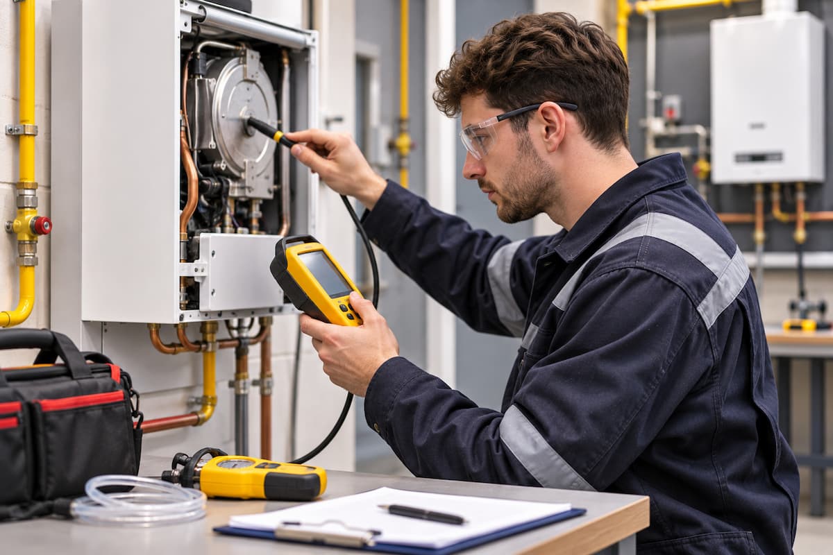
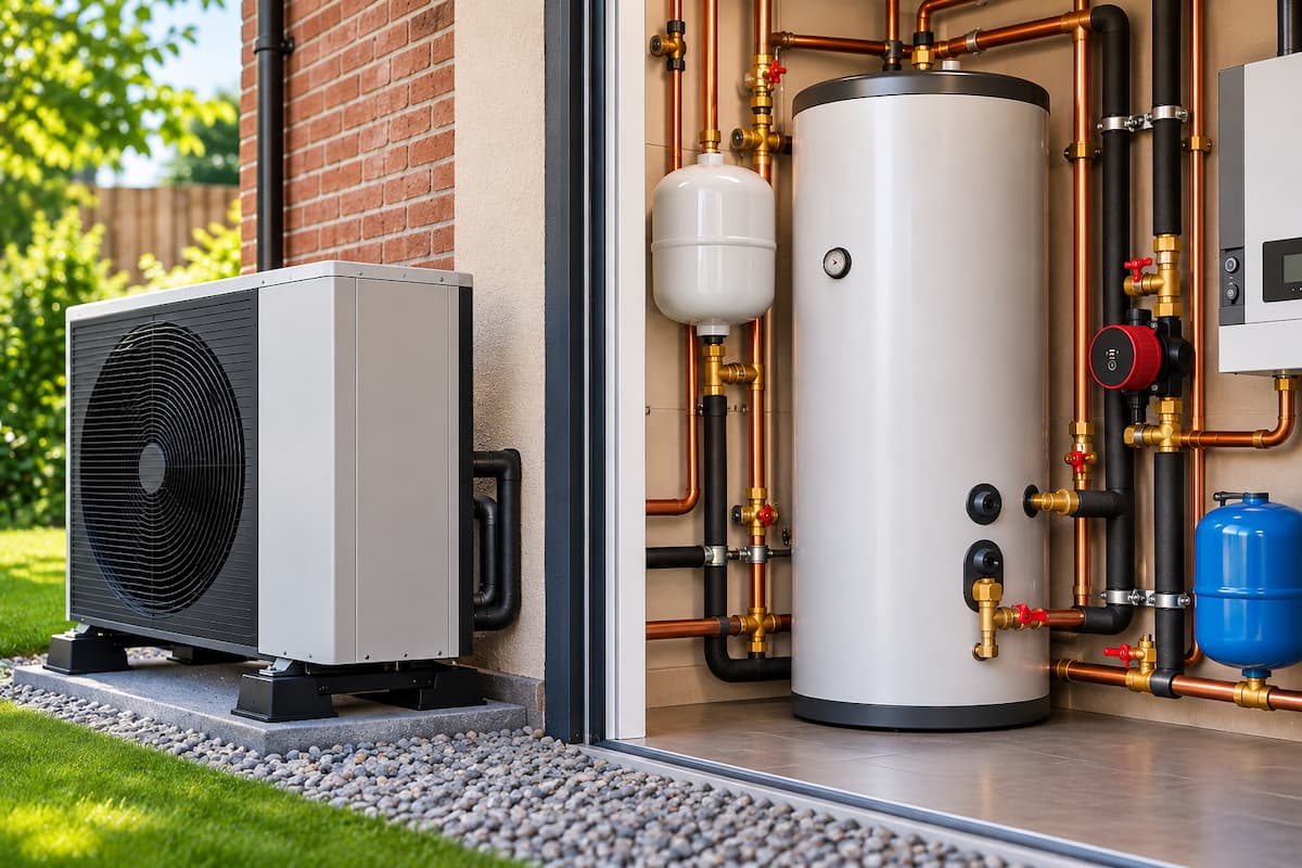
Selecting the correct hot water cylinder is an important part of designing an efficient heat pump installation. The cylinder must store enough hot water to meet household demand while allowing the heat pump to replenish that supply within a reasonable period.
Unlike conventional boiler systems, heat pumps generally operate with lower primary water temperatures. This affects the rate at which heat can be transferred into a hot water cylinder and makes heat exchanger performance particularly important.
A cylinder that appears suitable based on storage capacity alone may deliver disappointing results if its internal coil cannot transfer sufficient heat from the heat pump. Equally, installing a much larger cylinder than necessary can increase standing heat losses, installation costs and the space required for the system.
For renewable heating engineers, cylinder selection involves assessing peak hot water demand, usable stored volume, heat pump output, coil performance and recovery time together.
This guide examines the calculations and practical considerations involved in sizing hot water cylinders for heat pump installations, including worked examples and commissioning checks.
Heat Pump Cylinder Sizing Requirements
Cylinder sizing begins with establishing the property’s domestic hot water demand.
The number of occupants provides a useful starting point, but it does not establish the volume of hot water required. Household routines, shower flow rates, bath capacity and simultaneous outlet use can all influence the amount of stored water needed.
For example, a household with four occupants taking short showers at different times may have a lower peak demand than a two-person household regularly using a large bath and a high-flow shower.
Installers should establish:
- The number of regular occupants and likely future changes.
- The number and type of showers, baths and other hot water outlets.
- The flow rates and typical duration of showers.
- The volume of water required to fill baths.
- Periods of simultaneous or consecutive hot water use.
- The time available for cylinder recovery between periods of demand.
- The intended storage temperature and water hygiene requirements.
The distinction between daily consumption and peak demand is particularly important.
A property may use 250 litres of mixed hot water throughout the day without requiring a cylinder capable of supplying that volume continuously. If demand is spread across several hours, the heat pump may have sufficient time to replenish the stored energy.
However, where several outlets are used consecutively, the cylinder must provide enough usable hot water before recovery becomes a limiting factor.
Calculating Hot Water Demand
Shower flow rates and usage duration provide a practical way to estimate demand.
The basic calculation is:
Water volume (litres) = Flow rate (litres/minute) × Duration (minutes)
Consider a shower operating at 9 litres per minute for eight minutes.
9 × 8 = 72 litres
The shower uses approximately 72 litres of mixed water.
If three occupants use the same shower consecutively, the total mixed water demand becomes:
72 × 3 = 216 litres
This does not mean the property automatically requires a cylinder with a 216 litre storage capacity.
The cylinder stores water at a temperature above the required shower temperature. Mixing that water with cold water increases the total volume available at the outlet.
The relationship between stored and mixed water temperatures must therefore be included in the calculation.
Stored Water Volume and Mixed Water Demand
A hot water cylinder may store water at 50°C, while a shower operates at approximately 40°C.
This difference allows cold water to mix with the stored hot water before it reaches the outlet.
A simplified calculation for the volume of hot water required is:
Hot water volume = Mixed water volume × (Mixed temperature − Cold temperature) ÷ (Hot temperature − Cold temperature)
Consider the following conditions:
- Mixed shower water demand: 216 litres
- Required shower temperature: 40°C
- Cylinder storage temperature: 50°C
- Incoming cold water temperature: 10°C
The calculation becomes:
216 × (40 − 10) ÷ (50 − 10)
216 × 30 ÷ 40 = 162 litres
Under ideal mixing conditions, approximately 162 litres of water stored at 50°C would be required to provide 216 litres at 40°C.
This demonstrates that mixed outlet demand and cylinder storage volume are different quantities.
However, the calculation assumes that the stored water remains at a uniform usable temperature and that all the theoretical hot water volume can be extracted.
In practice, the available volume is affected by cylinder stratification, incoming cold water mixing, outlet flow rate and the temperature at which the delivered water becomes unsuitable.
For this reason, use manufacturer draw-off performance data when selecting a cylinder.
Cylinder Draw Off Performance
Cylinder manufacturers may provide performance figures showing the volume of usable hot water available under specified test conditions.
These figures can be more useful than nominal cylinder capacity because they account for the cylinder’s actual behaviour during hot water extraction.
Where available, installers should examine performance information such as the volume of mixed water delivered at a specified temperature, draw-off rate and initial storage temperature.
Care is needed when comparing different manufacturers because the test conditions may not be identical.
A cylinder delivering a high mixed water volume at a relatively low draw-off rate may perform differently when supplying several high-flow outlets.
Comparing Cylinder Storage Capacities
Domestic heat pump cylinders are available in a range of capacities, commonly including 150, 200, 250, and 300 litre models.
Larger cylinders provide greater potential stored energy, but they also require more heat to raise the entire contents through a given temperature difference.
The following table illustrates the theoretical energy required to heat different water volumes from 10°C to 50°C.
| Cylinder Capacity | Temperature Rise | Energy Required |
|---|---|---|
| 150 litres | 40°C | 7.0kWh |
| 200 litres | 40°C | 9.3kWh |
| 250 litres | 40°C | 11.6kWh |
| 300 litres | 40°C | 13.9kWh |
These values are calculated using the approximate specific heat capacity of water.
Energy (kWh) = Volume (litres) × 4.18 × Temperature rise (°C) ÷ 3600
The figures represent theoretical heating energy rather than the electricity consumed by the heat pump.
Actual electricity consumption depends on the heat pump’s coefficient of performance, operating conditions, supplementary heating and system losses.
Cylinder Coil Performance and Heat Transfer
The internal heat exchanger coil transfers heat from the heat pump’s primary circuit into the stored domestic water.
Its performance is particularly important because heat pumps typically supply water at lower temperatures than conventional boilers.
A cylinder designed for a boiler may have a coil capable of transferring substantial heat when supplied with primary water at 75°C or 80°C. The same coil may transfer considerably less heat when supplied at 50°C or 55°C.
Heat transfer depends on several factors:
- The effective surface area of the heat exchanger.
- The temperature difference between primary water and stored water.
- The primary water flow rate through the coil.
- The coil’s construction and heat transfer characteristics.
- The hydraulic resistance of the coil.
- The changing temperature of the stored water during recovery.
Heat pump cylinders commonly incorporate larger heat exchanger surfaces to improve performance at lower primary temperatures.
However, a larger coil does not automatically guarantee better results. The complete cylinder performance must be checked against the proposed heat pump.
Heat Pump Output Versus Coil Capacity
Consider an air source heat pump with a nominal thermal output of 8kW.
The installer selects a cylinder whose coil is advertised as having a 20kW rating.
At first glance, the coil appears more than capable of transferring the heat pump’s output.
However, the 20kW figure may have been established using boiler operating temperatures considerably higher than those available from the heat pump.
At lower primary temperatures, the actual heat transfer capacity could be substantially reduced.
The installer must therefore check the conditions associated with the published rating rather than comparing the two nominal outputs directly.
A suitable cylinder should be able to transfer the heat pump’s available thermal output under the intended operating conditions, allowing for the changing temperature difference during recovery.
Manufacturer Performance Data
Cylinder manufacturers may provide coil ratings, heat transfer figures and recovery times based on defined primary and stored water temperatures.
The most useful information is performance data that closely matches the proposed installation.
| Manufacturer Data | Importance For Cylinder Selection |
|---|---|
| Nominal cylinder capacity | Establishes the approximate stored water volume |
| Heat exchanger surface area | Provides an indication of available heat transfer surface |
| Coil heat transfer rating | Indicates thermal performance under specified test conditions |
| Primary flow temperature | Allows comparison with the heat pump’s operating temperature |
| Primary flow rate | Identifies the circulation conditions required for published performance |
| Coil pressure loss | Supports circulation pump and hydraulic design |
| Recovery time | Indicates heating performance under stated test conditions |
| Mixed water draw off performance | Helps establish usable hot water availability |
| Standing heat loss | Supports comparison of stored water heat losses |
Where manufacturers provide several performance ratings, installers should select the figures that most closely match the intended primary flow temperature, flow rate, and cylinder temperature.
If suitable data is unavailable, obtain clarification from the manufacturer before confirming the cylinder specification.
Heat Pump Cylinder Recovery Times
Cylinder recovery time describes the period required to restore the stored water to its target temperature following hot water use.
Recovery performance is influenced by the amount of energy required and the average rate at which heat is transferred into the water.
The theoretical calculation is:
Recovery time (hours) = Energy required (kWh) ÷ Average heat transfer rate (kW)
For example, a 200 litre cylinder heated from 10°C to 50°C requires approximately 9.3kWh.
If the average heat transfer rate into the stored water is 5kW:
9.3 ÷ 5 = 1.86 hours
This is approximately 112 minutes.
The calculation assumes a constant average transfer rate. Actual recovery may be longer or shorter depending on the heat pump output, cylinder performance, operating temperatures and control behaviour.
Importantly, the heat pump’s nominal rated output should not automatically be used as the average cylinder heating output.
Recovery Time Comparison
The following table compares theoretical recovery times for different cylinder capacities, assuming a constant average heat transfer rate of 5kW and a temperature rise from 10°C to 50°C.
| Cylinder Capacity | Energy Required | Theoretical Recovery Time |
|---|---|---|
| 150 litres | 7.0kWh | 84 minutes |
| 200 litres | 9.3kWh | 112 minutes |
| 250 litres | 11.6kWh | 139 minutes |
| 300 litres | 13.9kWh | 167 minutes |
These calculations demonstrate the relationship between storage capacity and the energy needed for a complete temperature rise.
They do not represent guaranteed recovery times for particular cylinder models.
A cylinder that has only been partially depleted will normally require less energy to recover than one whose entire contents have cooled to the incoming cold water temperature.
Recovery Performance at Different Temperatures
The temperature difference between the primary heating water and the stored domestic water strongly influences heat transfer.
At the beginning of a cylinder heating cycle, the stored water may be relatively cool. This creates a larger temperature difference across the heat exchanger coil and can support a higher transfer rate.
As the stored water warms, the temperature difference decreases.
For example, consider a cylinder being heated using primary water supplied at 55°C.
| Illustrative Cylinder Temperature | Difference From 55°C Primary Flow | Heat Transfer Implication |
|---|---|---|
| 20°C | 35°C | Greater potential temperature difference for heat transfer |
| 30°C | 25°C | Heat transfer potential reduces as the cylinder warms |
| 40°C | 15°C | Further reduction in available temperature difference |
| 50°C | 5°C | Limited temperature difference can restrict final recovery |
This comparison uses the primary flow temperature as a simplified reference. The actual heat transfer rate depends on the temperature distribution within the cylinder and the primary flow and return temperatures.
It does not establish the precise heat transfer output at each stage.
The final portion of the heating cycle can be particularly demanding because the heat pump may need to maintain a relatively high primary temperature. At the same time, the coil transfers progressively less heat.
Some systems increase primary flow temperature during recovery, subject to their controls and operating limits.
This is one reason manufacturer recovery figures are preferable to calculations based on a fixed heat transfer rate.
Primary Water Flow and Coil Resistance
Adequate primary water flow is necessary for effective heat transfer through the cylinder coil.
The flow rate required depends on the heat transfer duty and the intended temperature difference between the primary flow and return.
For water, an approximate relationship is:
Thermal output (kW) = 4.18 × Flow rate (litres/second) × Temperature difference (°C)
Consider a cylinder coil transferring 6kW with a primary temperature difference of 5°C.
Flow rate = 6 ÷ (4.18 × 5)
Flow rate = 0.287 litres/second
This is approximately 17.2 litres per minute.
The calculation provides an illustrative flow requirement for the stated duty and temperature difference. The actual design flow must also satisfy the heat pump and cylinder manufacturers’ requirements.
The circulation pump must overcome the resistance of the cylinder coil, connecting pipework, valves and other components.
An undersized pipe or restrictive heat exchanger can reduce primary flow, limiting the rate of heat transfer into the cylinder.
The relationship between flow rate, pressure loss and pump performance is also important in heat pump hydraulic separation, particularly where different circuits have separate circulation requirements.
Cylinder Sizing For Different Household Demands
Cylinder selection should reflect the pattern of hot water use rather than relying on a fixed litres per person rule.
The following examples illustrate the design considerations for different properties.
Property With Moderate Hot Water Demand
Consider a property with two occupants using a standard shower at separate times during the day.
The installer establishes that peak demand is relatively modest and that there is sufficient time between periods of use for cylinder recovery.
A 150 or 200 litre cylinder might be considered, depending on shower flow rate, required mixed water volume, storage temperature and manufacturer performance data.
A smaller cylinder may provide adequate performance where demand is predictable, and the heat pump can restore the stored energy between uses.
Family Property With Consecutive Showers
A family of four may regularly use several showers within a short morning period.
The installer calculates the mixed water demand using the measured or specified shower flow rates and expected duration.
A 200 or 250 litre cylinder might be considered initially, but the final selection depends on the usable draw-off volume and recovery performance.
If demand is concentrated into a short period, additional storage may be more valuable than rapid recovery alone.
Property With High Bathing Demand
A property with a large bath, multiple bathrooms, or high-flow showers may require a greater volume of stored hot water.
The installer should establish the actual bath filling volume and the potential for simultaneous use.
A 250 or 300 litre cylinder may be appropriate for some installations, but capacity alone does not establish suitability.
The available cold water supply, outlet flow rates, cylinder draw-off performance and heat pump recovery capability must all be checked.
These examples illustrate the selection process rather than providing fixed cylinder sizes for particular household types.
Oversizing and Undersizing Heat Pump Cylinders
Both undersized and oversized cylinders can create performance problems.
An undersized cylinder may not provide sufficient hot water during peak demand, even where the heat pump and heat exchanger operate correctly.
Occupants may experience falling outlet temperatures or need to wait for the cylinder to recover before using another shower or bath.
Oversizing creates different considerations.
A larger cylinder requires more installation space and may have greater standing heat losses, depending on its construction and insulation. Heating the entire stored volume through a given temperature rise also requires more energy.
However, a larger cylinder is not automatically inefficient. Additional storage can be useful where peak demand is high, recovery periods are limited or electricity tariffs favour heating at particular times.
The important issue is whether the additional storage provides a practical benefit that justifies its cost and associated heat losses.
Cylinder Selection Mistakes
Several recurring mistakes can affect the performance of heat pump hot water installations.
| Selection Mistake | Potential Consequence |
|---|---|
| Choosing cylinder capacity solely from the number of bedrooms | Actual peak hot water demand may not be met |
| Using a boiler cylinder without checking coil performance | Insufficient heat transfer at lower primary temperatures |
| Comparing nominal coil ratings without checking test conditions | Overestimating heat exchanger capability |
| Using nominal heat pump output for every recovery calculation | Unrealistic recovery time estimates |
| Ignoring primary flow and coil pressure loss | Reduced circulation and heating performance |
| Assuming all stored water is available at the target outlet temperature | Overestimating usable hot water volume |
| Installing unnecessary storage capacity | Additional cost, space requirements and potentially greater heat losses |
Most of these problems can be avoided by combining a realistic demand assessment with manufacturer performance information.
Cylinder Sizing Example
Consider a four person household with an air source heat pump supplying space heating and domestic hot water.
The property has two bathrooms, and three occupants regularly shower during the morning.
The installer establishes the following design assumptions:
- Three consecutive showers.
- Shower flow rate of 9 litres per minute.
- Average shower duration of eight minutes.
- Required mixed water temperature of 40°C.
- Incoming cold water temperature of 10°C.
- Proposed cylinder storage temperature of 50°C for the initial demand calculation.
Step 1: Calculate Mixed Water Demand
Each shower uses:
9 × 8 = 72 litres
Three showers require:
72 × 3 = 216 litres
The peak mixed water demand is therefore approximately 216 litres.
Step 2: Calculate Theoretical Stored Water Requirement
Using the simplified mixing calculation:
216 × (40 − 10) ÷ (50 − 10)
Required stored hot water = 162 litres
This represents the theoretical quantity of water at 50°C needed to provide the calculated mixed demand.
It does not include an allowance for imperfect draw-off performance or other simultaneous hot water use.
Step 3: Compare Cylinder Options
A 150 litre cylinder would contain less than the theoretical hot water requirement if no recovery occurred during the demand period.
A 200 litre cylinder provides a larger nominal stored volume, but the installer must confirm that its actual draw-off performance meets the required demand.
A 250 litre cylinder could provide additional storage, although its greater capacity may not be necessary if the 200 litre model satisfies the demand and recovery requirements.
Manufacturer draw-off data is needed before selecting between these options.
Step 4: Assess Recovery Performance
Suppose a 200 litre cylinder is selected for further assessment.
Heating its entire contents from 10°C to 50°C requires approximately 9.3kWh.
If the heat pump and cylinder combination achieves an average transfer rate of 6kW:
9.3 ÷ 6 = 1.55 hours
The theoretical full recovery time is approximately 93 minutes.
The installer then checks the manufacturer’s recovery information and considers whether the household has sufficient time between peak demand periods.
In practice, recovery after the morning showers depends on the remaining temperature distribution within the cylinder, not simply the full cylinder volume.
Step 5: Confirm Equipment Compatibility
Before finalising the selection, the installer checks that:
- The cylinder coil is suitable for the heat pump’s operating temperatures and output.
- The required primary flow can be maintained through the coil.
- The heat pump can achieve the intended storage temperature.
- The cylinder provides sufficient usable hot water at the required draw-off rate.
- The recovery performance meets the household’s usage pattern.
- The proposed operating arrangement supports the required water hygiene strategy.
The example demonstrates that the final cylinder choice depends on more than a calculated storage volume. The selected cylinder must provide the required usable water and recover within an acceptable period under actual heat pump operating conditions.
Commissioning and Recovery Time Verification
Cylinder sizing calculations should be supported by commissioning measurements once the installation is complete.
The installer should confirm that the cylinder, heat pump and primary circuit operate together as intended.
A representative recovery test can help identify problems with heat transfer, circulation or control settings.
The process should include recording the initial cylinder temperature, primary flow and return temperatures, relevant flow measurements and the time taken to reach the target.
Where the system provides energy monitoring, the recorded thermal output may also help assess performance.
Care is needed when interpreting the results because cylinder temperature sensors usually measure temperature at particular positions rather than providing an average temperature for the entire stored volume.
The measured recovery period should therefore be compared with manufacturer guidance and the actual starting conditions.
Commissioning Record
| Measurement | Required Record |
|---|---|
| Cylinder manufacturer and model | Installed cylinder specification |
| Nominal storage capacity | Litres |
| Heat exchanger specification | Manufacturer performance reference |
| Heat pump operating mode | Domestic hot water heating |
| Primary flow rate | Measured litres per minute |
| Primary flow temperature | Measured °C |
| Primary return temperature | Measured °C |
| Initial cylinder temperature | Measured °C and sensor location |
| Final cylinder temperature | Measured °C and sensor location |
| Recovery duration | Minutes |
| Supplementary heater operation | Operating status during test |
Accurate commissioning records are useful when investigating future complaints about insufficient hot water or slow cylinder recovery.
The wider heat pump commissioning process should also verify controls, safety arrangements and the intended operating configuration.
Diagnosing Poor Cylinder Recovery
If a cylinder takes longer than expected to recover, establish the cause before increasing the storage temperature or enabling additional immersion heating.
Possible causes include insufficient heat pump output under the operating conditions, restricted primary flow, poor heat exchanger performance or incorrect control settings.
| Observed Problem | Possible Cause | Recommended Investigation |
|---|---|---|
| Long recovery time | Insufficient heat transfer through the coil | Compare operating temperatures and flow with manufacturer data |
| High primary flow temperature but slow cylinder heating | Coil limitation or circulation restriction | Check primary flow, return temperature and coil specification |
| Heat pump output lower than expected | Operating conditions or control limitations | Check available thermal output and operating parameters |
| Cylinder heating stops prematurely | Temperature sensor or control configuration issue | Verify sensor positioning and settings |
| Frequent immersion heater operation | Insufficient compressor heating performance or control settings | Review supplementary heating configuration and temperature requirements |
| Insufficient hot water despite normal recovery | Peak demand exceeds usable storage | Reassess draw-off volume and household demand |
These investigations should form part of a systematic diagnostic process. The principles of heat pump fault finding are particularly relevant where circulation, temperature control and heat pump output interact.
Heat Pump Training In Staffordshire
Correct cylinder sizing requires an understanding of domestic hot water demand, heat transfer, primary circulation and heat pump operating characteristics.
Installers must be able to interpret manufacturer specifications, calculate heating requirements and assess whether the proposed equipment will deliver suitable performance.
At Staffordshire Training Services, the Low Temperature Heating and Hot Water Systems Level 3 Course supports engineers developing their knowledge of heating system design and domestic hot water requirements.
Engineers looking to develop their renewable installation skills can also undertake the Air Source Heat Pump Systems Level 3 Focused Course or the Air and Ground Source Heat Pump Systems Level 3 Combined Course.
Training at our centre in Stafford helps engineers build the practical knowledge to assess system requirements, select suitable equipment, and commission installations confidently.
A correctly sized heat pump cylinder should provide sufficient usable hot water for the household while allowing the heat pump to recover stored energy within an acceptable period. Combining demand calculations with manufacturer performance data and commissioning measurements gives installers a more reliable basis for cylinder selection than nominal storage capacity alone.
Related Articles
- Hot Water Cylinders Explained
- Heat Pump Circulation Pumps and Flow Rates
- Hydraulic Separation in Heat Pump Systems
- Heat Pump Commissioning Procedures for Renewable Installers
- Heat Pump Fault Finding for Renewable Installers
Prefer an AI Summary?