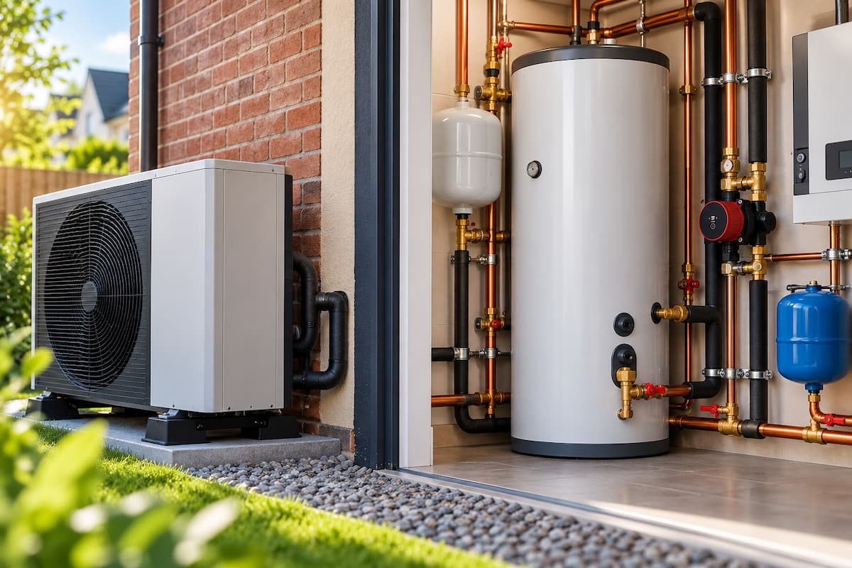
Hydraulic design directly influences heat pump performance. A heat pump requires sufficient water flow through its heat exchanger. At the same time, the heating circuits within the property must distribute that energy effectively through radiators, underfloor heating or a combination of emitters.
In a relatively straightforward installation, these requirements can often be achieved using a single hydraulic circuit. As systems become more complex, circulation pumps, zone valves, thermostatic controls, and circuits with different flow requirements can begin to interact.
Hydraulic separation allows different parts of the heating system to operate with a degree of hydraulic independence. It can help maintain the flow required by the heat pump while allowing distribution circuits to respond to changing heating demand within the property.
For renewable installers, the important skill is not simply knowing where to install a hydraulic separator. It is recognising where separation is required, selecting a suitable arrangement and commissioning the system so that primary and secondary flow rates support efficient heat pump operation.
Hydraulic Separation Principles
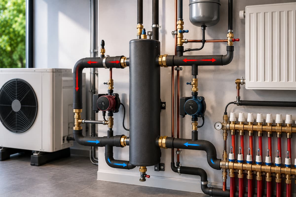
Hydraulic separation divides a heating system into circuits that can operate at different flow rates without one circulation pump significantly affecting another.
A typical arrangement consists of a primary circuit serving the heat pump and a secondary circuit supplying the heating emitters. The primary circulation pump moves water through the heat pump, while the secondary circulation pump moves water through radiators, underfloor heating, or other heating circuits.
A hydraulic separator provides a low-resistance connection between the circuits. This allows each circulation pump to operate primarily against the resistance of the circuit it serves.
The basic principle can be represented as follows:
HYDRAULIC
SEPARATOR
│
│
HEAT PUMP FLOW ─────►│─────► SECONDARY FLOW
│
PRIMARY │ SECONDARY
CIRCUIT │ CIRCUIT
│
HEAT PUMP RETURN ◄───│◄───── HEATING RETURN
│
│
RADIATORS
+
UNDERFLOOR HEATING
The heat pump circuit and heating distribution circuit remain thermally connected through the water, but their circulation pumps are hydraulically separated.
Hydraulic separation does not create additional heat or automatically increase efficiency. Its purpose is to manage water movement through the system.
Primary and Secondary Circuits
The primary circuit generally refers to the pipework between the heat pump and hydraulic separation point. It maintains the flow conditions required by the heat pump manufacturer.
The secondary circuit distributes heated water from the separation point to the property. Depending on the installation, it may contain radiators, underfloor heating manifolds, several heating zones or multiple circulation pumps.
The relationship can be represented more clearly as:
PRIMARY CIRCUIT SECONDARY CIRCUIT
┌──────────────┐ ┌──────────────────┐
│ │ ┌─────────┐ │ │
│ HEAT PUMP │─────►│ │──────►│ Radiators │
│ │ │Hydraulic│ │ │
│ │◄─────│Separator│◄──────│ Underfloor │
└──────────────┘ │ │ │ Heating │
▲ └─────────┘ └──────────────────┘
│ ▲
PRIMARY PUMP SECONDARY PUMP
This arrangement becomes particularly useful where the heat pump requires a stable minimum flow while the distribution system experiences changing demand.
The hydraulic arrangement must also complement the wider low temperature heating system. Hydraulic separation cannot compensate for unsuitable emitters, excessive design temperatures or inadequate pipework.
Heat Pump Flow Requirements
Every heat pump has a required operating flow range. Manufacturers may specify a minimum flow rate that must pass through the heat exchanger whenever the compressor is operating.
If flow falls below this requirement, heat transfer can deteriorate, and the heat pump may generate a flow-related fault.
Reduced flow can result from closed zone valves, thermostatic radiator valves, blocked filters, incorrectly selected pumps, undersized pipework or poor hydraulic balancing.
Hydraulic separation can protect the primary circuit from some of these variations because the heat pump circulation pump can maintain its required flow independently of changing secondary heating demand.
It should not be used as a substitute for correct pipe sizing, pump selection or balancing. Flow verification should form part of heat pump commissioning procedures so the completed installation can demonstrate that manufacturer requirements are being achieved.
Circulation Pump Interaction
Multiple circulation pumps operating within the same hydraulic circuit can influence each other.
If pumps have different duties or operate at different speeds, one may alter the pressure conditions the other experiences. This can produce unexpected flow rates through the heat pump or heating circuits.
Possible effects include noise, poor circulation, unstable flow, uneven heating and difficulty balancing the system.
Hydraulic separation creates a low-resistance point between the circuits. Each pump can then primarily respond to the resistance of the circuit it serves.
This can make systems containing several circulation pumps easier to design and commission, although pump selection remains important. Hydraulic separation does not remove the need to calculate each circuit’s required flow and pressure characteristics.
Changing Heating Demand
Hydraulic conditions within a property rarely remain fixed throughout the heating period.
Thermostatic radiator valves may open and close. Underfloor heating actuators can shut individual loops. Motorised zone valves may isolate entire sections of the property.
Each change affects resistance and flow within the distribution system.
Where the heat pump is connected directly to these circuits, changes in secondary flow can affect flow through the heat pump itself.
A hydraulically separated arrangement lets the secondary side respond to changing heating demand while keeping conditions on the primary side more stable.
This can be particularly useful in larger properties and installations containing several independently controlled heating zones.
Methods of Hydraulic Separation
Hydraulic separation can be achieved using several arrangements. The appropriate method depends on the heating design, required system volume, number of circuits and manufacturer instructions.
Installers may encounter low loss headers, dedicated hydraulic separators and four port buffer vessels.
Each performs a similar hydraulic function, but their effect on system water volume and installation requirements differs.
| System Arrangement | Hydraulic Separation | Additional Water Volume | Typical Application |
|---|---|---|---|
| Direct Circuit | No | No | Simple heating systems with stable flow |
| Volumiser | No | Yes | Systems requiring additional water volume |
| Four Port Buffer Vessel | Yes | Yes | Systems requiring separation and additional volume |
| Low Loss Header | Yes | Limited | Systems with multiple circuits or circulation pumps |
Component selection should follow the installation’s hydraulic requirements rather than treating these devices as interchangeable.
Four Port Buffer Vessels
A four port buffer vessel in a heat pump installation can provide hydraulic separation while also increasing system water volume.
Two connections serve the heat pump circuit, and two serve the distribution circuit.
A simplified arrangement looks like this:
FOUR PORT BUFFER VESSEL
HEAT PUMP FLOW ─────►┌──────────────┐─────► HEATING FLOW
│ │
│ BUFFER │
│ VESSEL │
│ │
HEAT PUMP RETURN ◄────└──────────────┘◄───── HEATING RETURN
PRIMARY SECONDARY
CIRCUIT CIRCUIT
This arrangement can be useful where both hydraulic separation and increased thermal mass are required.
The additional water volume can help satisfy manufacturer requirements and may reduce compressor cycling where the existing system volume is insufficient.
The vessel still needs to be sized and connected correctly. Installing a buffer vessel simply because a heat pump is present can add heat loss, cost, and complexity without providing a meaningful benefit.
Low Loss Headers
A low loss header provides a low resistance connection between primary and secondary circuits.
The heat pump circulation pump moves water through the primary side while one or more secondary pumps distribute water through the heating circuits.
Unlike a larger buffer vessel, a low loss header adds relatively little water volume. Its principal role is hydraulic, not to provide additional thermal mass.
If you also need more system water volume, the installer must address it separately.
This distinction matters because insufficient system volume and hydraulic interaction are different design problems.
Volumisers and Hydraulic Separation
A volumiser does not provide hydraulic separation.
It is installed in series with the heating circuit, increasing total system water content while maintaining a direct hydraulic connection between the heat pump and emitters.
The difference can be visualised:
VOLUMISER
HEAT PUMP ───► VOLUMISER ───► HEATING SYSTEM
▲ │
└──────────────────────────────┘
One continuous hydraulic circuit
HYDRAULIC SEPARATOR
HEAT PUMP ───►│ SEPARATOR │───► HEATING SYSTEM
▲ │ │ │
└──────────│ │◄──────────┘
Primary and secondary circuits
This distinction is important because insufficient system volume and unstable hydraulic flow are different problems.
If you only need additional water volume, a volumiser may be the simpler solution. If you need independent primary and secondary circulation, you may need hydraulic separation.
Flow Matching
One of the most important considerations in hydraulically separated heat pump systems is the relationship between primary and secondary flow.
Hydraulic separation allows these flows to differ, but the size and direction of that difference still matter.
Three broad operating conditions can occur:
| Primary Flow | Secondary Flow | Result |
|---|---|---|
| Approximately equal | Approximately equal | Minimal internal mixing |
| Higher | Lower | Primary flow mixes into the return |
| Lower | Higher | Secondary return mixes into the heating flow |
The third condition deserves particular attention because it can reduce the temperature reaching the heating emitters.
Equal Primary and Secondary Flow
Where primary and secondary flow rates are approximately equal, most heated water leaving the heat pump passes directly into the heating circuit.
Return water from the heating circuit returns to the heat pump with relatively little internal mixing.
PRIMARY FLOW 20 L/min SECONDARY FLOW 20 L/min
─────────────►│ │─────────────►
│ SEPARATOR│
◄─────────────│ │◄─────────────
PRIMARY RETURN SECONDARY RETURN
This condition generally minimises unwanted temperature mixing across the separation point.
Perfect flow matching is unlikely throughout every operating condition, particularly where heating zones open and close, but the principle is valuable during commissioning.
Excess Primary Flow
If primary flow exceeds secondary demand, more heated water arrives at the separator than the heating circuit requires.
For example:
PRIMARY FLOW SECONDARY FLOW
30 L/min 20 L/min
─────────────►│ │────────────►
│ │
│ │ │
│ ▼ │
│ 10 L/min │
│ recirculates│
◄─────────────│ │◄────────────
The excess primary water travels down through the separator and mixes with the cooler secondary return before returning towards the heat pump.
This can raise the temperature of water returning to the heat pump.
Installers should therefore avoid assuming that hydraulic separation removes the need to assess flow rates.
Excess Secondary Flow
A particularly important condition occurs where secondary flow exceeds primary flow.
Imagine the heat pump circuit supplying 20 litres per minute while the secondary circuit requires 30 litres per minute.
The additional 10 litres per minute must come from somewhere.
It is drawn from the secondary return through the hydraulic separator:
PRIMARY FLOW SECONDARY FLOW
20 L/min at 40°C 30 L/min
─────────────►│ │────────────►
│ │
│ ▲ │
│ │ │
│ 10 L/min │
│ cooler return│
◄─────────────│ │◄────────────
│ │
└──────────────┘
The secondary flow is therefore a mixture of hot water arriving from the heat pump and cooler water returning from the emitters.
This produces temperature dilution.
Temperature Dilution
Temperature dilution is particularly important in low-temperature heating systems because small temperature changes can affect emitter output.
Consider a heat pump supplying water at 40°C.
If the primary circuit supplies 20 litres per minute while the secondary circuit requires 30 litres per minute, the separator must draw 10 litres per minute of secondary return water.
If that return water is at 30°C, the secondary flow temperature will be lower than the 40°C leaving the heat pump.
The principle can be represented as:
HEAT PUMP
20 L/min at 40°C
│
▼
┌────────────┐
│ HYDRAULIC │────────► SECONDARY FLOW
│ SEPARATOR │ 30 L/min
│ │
│ ▲ │
│ │ │
│ 10 L/min │
│ at 30°C │
└─────┬──────┘
│
COOLER RETURN
The emitters therefore receive a mixture rather than the full 40°C heat pump flow.
If you selected the emitters assuming they would receive 40°C water, their available output may fall. Correct radiator sizing for heat pumps remains essential. Still, even a correctly selected radiator cannot provide its calculated output if its actual entering water temperature is below the design condition.
An installer may be tempted to increase the heat pump target temperature to compensate. This can reduce heat pump efficiency even though the original issue is hydraulic.
Temperature Measurement During Commissioning
Temperature measurements provide valuable evidence about the behaviour of a hydraulically separated system.
Installers should consider measuring four temperatures:
T2
SECONDARY FLOW
│
▼
T1 ─────────► ┌─────────────┐
HEAT PUMP │ HYDRAULIC │
FLOW │ SEPARATOR │
└─────────────┘ ◄──────── T3
│ SECONDARY
▼ RETURN
T4
HEAT PUMP
RETURN
Comparing T1 with T2 can identify temperature dilution across the separation point.
Comparing T3 with T4 can provide further information about internal mixing.
Consider these readings alongside measured flow rates and the operating state of individual heating zones. Measurements taken after the system has stabilised are generally more useful than readings taken immediately after start-up.
Multiple Heating Zones
Hydraulic separation becomes particularly relevant where several heating zones operate independently.
A property may contain separate zones for upstairs radiators, downstairs underfloor heating and an extension.
As individual zones open and close, secondary flow requirements change.
If all circuits operate directly from the heat pump circulation pump, maintaining suitable flow through every possible combination can become difficult.
A separate system lets the primary heat pump circuit operate independently while secondary pumps manage individual heating zones.
However, the control strategy must still prevent the heat pump from operating when heating demand is insufficient. Hydraulic separation cannot compensate for unsuitable zoning or poor control logic.
Radiators and Underfloor Heating
Properties containing both radiators and underfloor heating can present additional hydraulic challenges.
The two emitter types may have different flow requirements, pressure losses and control arrangements. Underfloor heating may also incorporate manifolds, actuators and dedicated circulation equipment.
Hydraulic separation can provide a practical way to allow these circuits to operate independently.
However, modern heat pump systems should be designed to operate at the lowest practical flow temperature. Introducing unnecessary mixing arrangements that raise the required heat pump temperature can undermine this objective.
Emitter selection should therefore begin with accurate heat loss calculations and suitable low temperature outputs before the hydraulic arrangement is finalised.
Direct Heat Pump Systems
Hydraulic separation is not automatically required simply because a heat pump is installed.
A direct system can offer several advantages where the hydraulic design permits it. Fewer pumps reduce electrical consumption, while less pipework reduces installation complexity. Eliminating unnecessary vessels and headers can also reduce standing heat losses.
A direct arrangement may look like this:
┌─────────────┐ ┌─────────────┐
│ │ │ │
│ HEAT PUMP │────────────────────────►│ EMITTERS │
│ │ │ │
│ │◄────────────────────────│ │
└─────────────┘ └─────────────┘
ONE CONTINUOUS HYDRAULIC CIRCUIT
Direct systems may be suitable where the heat pump can maintain sufficient flow under all operating conditions and the heating circuits do not require independent hydraulic control.
Manufacturer requirements should remain the starting point for deciding whether a direct or separated arrangement is appropriate.
Hydraulic Separation and Weather Compensation
Hydraulic separation also needs to be considered alongside weather compensation and heat pump efficiency.
Weather compensation adjusts the target flow temperature according to outdoor conditions. During milder weather, the heat pump may produce considerably cooler water because the property requires less heat.
If temperature dilution occurs across the hydraulic separator, the secondary circuit could receive water at an even lower temperature than the weather compensated leaving water temperature.
An installer might respond by raising the heating curve, but this can conceal the hydraulic issue and increase flow temperatures across the heating season.
Checking the actual temperature delivered to the emitters alongside the heat pump leaving water temperature is therefore valuable when optimising a separated system.
Hydraulic Separation and Efficiency
Hydraulic separation should support efficient operation rather than being treated as an efficiency measure in itself.
Additional circulation pumps consume electricity. Buffer vessels and associated pipework introduce additional surfaces from which heat can escape. Flow mismatch can create temperature dilution.
These effects do not mean you should avoid hydraulic separation. They demonstrate the importance of using it for a defined engineering purpose.
The preferred arrangement is generally the simplest hydraulic design that satisfies manufacturer requirements while providing reliable heating throughout the property.
Installation Considerations
Pipework must be sized to accommodate the required flow rates without excessive resistance. Select circulation pumps for the duties of their individual circuits, and position sensors so the control system receives representative temperature readings.
Insulation is also important. Buffer vessels, headers and associated pipework can operate for extended periods during the heating season, making poorly insulated components a source of avoidable heat loss.
Provision should also be made for air removal, draining, servicing and access to pumps and valves.
The installation layout should make commissioning and future diagnostic work practical rather than positioning components purely according to the available space.
Commissioning a Separated System
Commissioning should verify the operation of both primary and secondary circuits.
Installers should confirm that the heat pump receives the manufacturer’s required flow rate and that each heating circuit receives sufficient flow to deliver its calculated output.
Useful checks include system pressure, pump settings, flow rates, flow and return temperatures, zone operation and weather compensation settings. These should form part of the wider heat pump commissioning process rather than treating hydraulic separation as an isolated component check.
The system should also be observed under different operating conditions. Testing only with every zone open may miss problems that appear as individual zones close.
Commissioning should therefore consider the range of hydraulic conditions the system will encounter during normal use.
Fault Finding Hydraulic Problems
Hydraulic issues can sometimes resemble faults within the heat pump itself.
Poor room temperatures, frequent cycling, flow alarms and excessive electricity consumption may all originate from the wider heating system rather than the heat pump.
| Symptom | Area To Investigate |
|---|---|
| Heat pump flow faults | Primary flow rate, pump operation, filters and restrictions |
| Secondary flow temperature below heat pump flow temperature | Primary and secondary flow mismatch |
| Uneven room temperatures | Secondary balancing, zone flow rates and emitter sizing |
| Frequent compressor cycling | System volume, heating demand and control strategy |
| High electricity consumption | Flow temperature, temperature dilution and pump operation |
Measured data should guide diagnosis. Increasing temperatures or pump speeds without identifying the cause can mask the original problem while reducing efficiency elsewhere.
The wider diagnostic process is covered in heat pump fault finding for renewable installers, where hydraulic performance should be assessed alongside controls, sensors and operating data.
Installation Example
Consider a detached property fitted with an air source heat pump. Underfloor heating serves the ground floor, while low-temperature radiators serve the first floor.
Both circuits have independent circulation requirements and can operate separately according to room demand.
The heat pump manufacturer requires a minimum primary flow rate that must be maintained whenever the compressor operates.
Connecting every circuit directly could let changes on the secondary side affect flow through the heat pump. Hydraulic separation is therefore incorporated so that the primary pump can maintain the required heat pump flow while the distribution circuits operate independently.
During commissioning, the engineer finds that the secondary pump is moving considerably more water than the primary circuit.
The heat pump produces a 40°C leaving water temperature, but the temperature measured on the secondary flow is lower because return water is being drawn through the separator.
Rather than increasing the heat pump target temperature, the engineer reviews the secondary pump setting and balances the distribution circuits.
Bringing the primary and secondary flows closer to the required operating conditions reduces mixing and allows the emitters to receive a flow temperature closer to the design value.
This example demonstrates the value of treating hydraulic separation as part of the complete system design. Installing the separator is only one stage. Flow rates, pump duties, controls and commissioning determine whether the arrangement performs effectively.
Selecting The Hydraulic Arrangement
Deciding whether to use hydraulic separation should start with the requirements of the heat pump and heating distribution system.
Installers should establish the manufacturer’s required flow rate, available system volume, number of heating circuits, circulation pump requirements and expected changes in heating demand.
Where a direct circuit can maintain suitable flow under every operating condition, additional hydraulic separation may offer little benefit.
Where circuits require independent flow or several pumps would otherwise interact, hydraulic separation can provide a practical solution.
If you need additional water volume but not hydraulic separation, a volumiser may be the simpler option. Where both additional volume and separation are required, a suitable buffer vessel arrangement may meet both objectives.
The correct solution is therefore determined by the hydraulic requirement, not by the presence of the heat pump itself.
Heat Pump Training In Staffordshire
Hydraulic design is an important part of installing and commissioning efficient heat pump systems. Engineers need to consider more than individual components, as flow rates, emitters, circulation pumps, system volume, controls, and operating temperatures all affect overall performance.
At Staffordshire Training Services, the Air Source Heat Pump Systems Level 3 course provides training for engineers developing the skills required to work with air source heat pump installations. In contrast, the Ground Source Heat Pump Systems Level 3 course focuses on the requirements associated with ground source systems.
Engineers looking to develop competence across both technologies can consider the Air and Ground Source Heat Pump Systems Combined Course.
Heat pump training helps installers develop the technical and practical knowledge required to assess system design, hydraulic arrangements, installation and commissioning as connected parts of the same process. This is particularly valuable when working with properties containing multiple heating zones, low-temperature emitters, and independent circulation circuits.
For heating engineers developing their renewable skills, renewables training in Staffordshire provides a practical route towards working confidently with modern air source and ground source heat pump systems.
Related Articles
- Quick Heat Pump Guide for Installers
- Volumisers In Heat Pump Systems
- Heat Pump System Design Basics for Gas Engineers Transitioning to Renewables
- Buffer Vessels in Heat Pump Systems
- Heat Pump Fault Finding For Renewable Installers
Prefer an AI Summary?