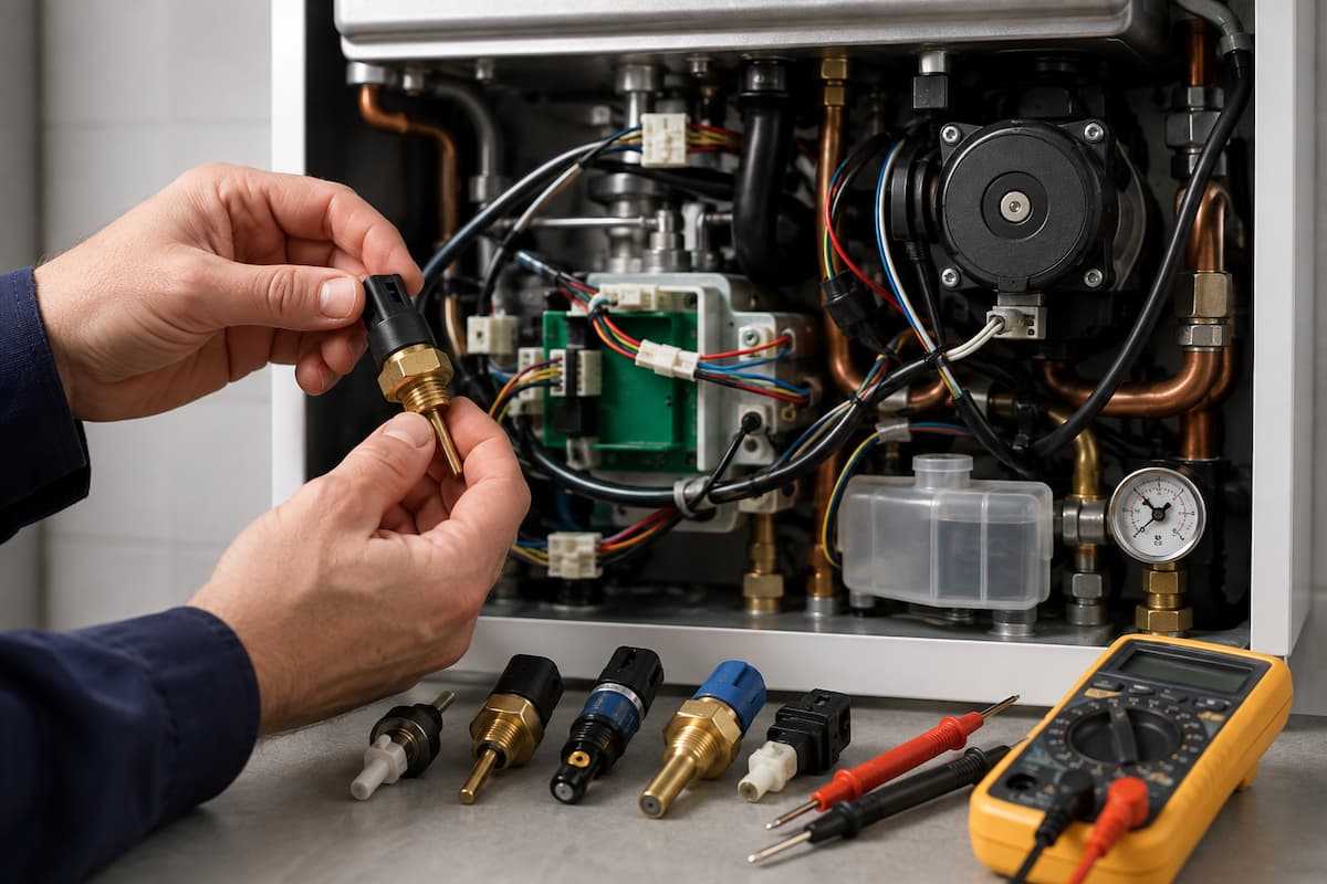
Modern boilers rely on a network of sensors to monitor temperature, water pressure, water flow, combustion conditions, and the operation of individual components. These sensors continuously provide information to the appliance control system, allowing the boiler to adjust its operation and respond if conditions move outside permitted limits.
For gas engineers, sensor faults can present a particular diagnostic challenge. A boiler may display a temperature, pressure or flow-related fault code, but this does not necessarily mean the corresponding sensor has failed. The sensor may simply be reporting a genuine problem elsewhere within the appliance or heating system.
A flow thermistor detecting a rapid temperature rise, for example, could be operating correctly while poor circulation causes the water temperature to increase. Replacing the thermistor would leave the original fault untouched.
Effective diagnosis therefore involves establishing three things: the physical condition being monitored, the electrical signal produced by the sensor and the information received by the PCB.
This article examines the sensors found across modern gas boilers, their operating principles and the testing techniques engineers can use to separate sensor faults from gas, hydraulic, electrical and appliance control problems.
Boiler Sensors
The PCB cannot directly measure water temperature, pressure, flow or component movement. It relies on sensors to convert physical conditions into electrical information that the control system can process.
Depending on the appliance, sensor information may influence:
- burner ignition
- burner modulation
- pump operation
- fan speed
- domestic hot water control
- central heating temperature
- overheat protection
- fault detection
- appliance shutdown
This means a single inaccurate sensor signal can influence several areas of boiler operation.
A temperature sensor that reports an incorrectly high value may cause the PCB to reduce burner output or shut the burner down. A pressure sensor reporting insufficient system pressure may prevent ignition altogether.
The PCB is responding to the information available to it. The engineer’s task is to establish whether that information accurately represents the condition inside the appliance.
Boiler Sensor Inputs
Sensors communicate with the PCB in several different ways.
Some components change resistance. Others generate or modify a voltage, produce pulses or change the state of an electrical circuit.
Typical boiler sensor arrangements include:
- resistance based temperature sensing
- pressure transducers
- Hall effect sensing
- reed switches
- flow turbines
- pressure switches
- rotational feedback
- flame ionisation signals
The precise design varies significantly between manufacturers and appliance generations.
Manufacturer technical information should therefore remain the primary reference for expected values, test procedures and connector arrangements.
Boiler Sensor Reference Table
| Boiler Sensor | Signal Or Principle | Information Supplied | Typical Diagnostic Checks |
|---|---|---|---|
| NTC Thermistor | Changing resistance | Water or component temperature | Resistance, temperature comparison, wiring |
| Water Pressure Sensor | Electronic voltage signal | System water pressure | Supply, signal, actual system pressure |
| Flow Turbine | Rotational or pulse signal | Domestic water movement | Water flow, turbine movement, sensor output |
| Hall Effect Sensor | Magnetic field detection | Movement or rotational position | Supply, signal, mechanical movement |
| Air Pressure Switch | Switching state | Pressure differential | Pressure source, tubing, switch operation |
| Fan Feedback | Electronic speed signal | Fan operation or rotational speed | Fan operation, wiring, feedback signal |
| Flame Sensor | Ionisation current | Flame presence | Microamp signal, electrode, earth path, flame quality |
Not every boiler contains all of these arrangements. Engineers should identify the system fitted to the appliance before beginning electrical diagnosis.
NTC Thermistors
NTC thermistors are among the most frequently encountered sensors in domestic boilers.
NTC stands for Negative Temperature Coefficient.
The operating principle is straightforward:
As temperature increases, resistance decreases.
Conversely:
As temperature decreases, resistance increases.
The PCB supplies power through the thermistor and interprets the resulting electrical characteristics as temperature.
The resistance relationship is not normally linear. A fixed temperature change does not produce the same resistance change at every point across the operating range.
For this reason, engineers should compare measured resistance with the manufacturer’s temperature and resistance data rather than estimating whether a reading appears reasonable.
Flow Temperature Thermistors
The central heating flow thermistor monitors the temperature of water leaving the boiler heat exchanger.
The PCB can use its information to control:
- burner modulation
- target flow temperature
- burner shutdown
- restart timing
- overheat prevention
During normal operation, the PCB continually monitors this temperature and adjusts burner output as the heating system approaches the required temperature.
Rapid Temperature Increase
Suppose the flow thermistor reports that water temperature rises extremely quickly after burner ignition.
It would be easy to interpret this as a temperature sensor fault.
However, a rapid genuine temperature rise can also result from:
- poor circulation
- pump problems
- closed valves
- restricted pipework
- blocked heat exchanger
- air within the system
The engineer should therefore confirm whether the pipe and water temperatures are actually rising before deciding the sensor is inaccurate.
If the physical temperature rise matches the sensor reading, the thermistor may be performing correctly.
The diagnostic direction should move towards the hydraulic system.
Return Temperature Thermistors
Many modern boilers also monitor the temperature of water returning from the heating system.
Comparing flow and return temperatures gives the control system additional information about heat transfer and system operation.
Depending on appliance design, this information may contribute to:
- modulation
- pump control
- heat exchanger protection
- appliance diagnostics
A return thermistor fault can produce misleading temperature information even though the flow sensor remains accurate.
Engineers should therefore identify which sensor a fault code or displayed temperature refers to before measuring.
Domestic Hot Water Thermistors
Combination boilers need accurate temperature information to control domestic hot water delivery.
A DHW thermistor may monitor the temperature of water leaving the appliance.
The PCB can then adjust burner output to maintain the required outlet temperature as water demand changes.
An inaccurate DHW thermistor may contribute to:
- fluctuating hot water temperature
- excessively hot water
- water failing to reach the selected temperature
- repeated burner cycling
- unexpected modulation
These symptoms can also result from hydraulic or combustion faults, making further diagnosis essential.
Flue Temperature Sensors
Some boilers incorporate sensors that monitor temperatures within the flue or combustion system.
Their purpose and operating limits depend on appliance design.
A flue temperature-related fault should not automatically be treated as sensor failure. The engineer should consider whether an abnormal temperature genuinely exists.
Potential areas requiring investigation may include:
- combustion condition
- heat exchanger performance
- flue system
- appliance cleanliness
- circulation
- sensor position
Manufacturer instructions should determine both the permitted operating range and the appropriate diagnostic procedure.
Testing NTC Thermistors
Resistance testing is one of the main ways to assess an NTC thermistor.
Safely isolate the appliance and follow the manufacturer’s procedure before measuring resistance.
Depending on the circuit, you may need to disconnect the thermistor to prevent other electrical paths from affecting the result.
Establishing Sensor Temperature
A resistance measurement is only useful if the engineer also has a reasonable indication of the sensor temperature.
For example, recording a resistance of 8 kω provides limited diagnostic information on its own.
The engineer needs to know:
- the approximate sensor temperature
- the manufacturer’s expected resistance at that temperature
You can then compare the measured value with the appliance data.
Worked Thermistor Example
A boiler displays a flow temperature of 75°C shortly after starting from cold.
Physical checks indicate that the flow pipe is still relatively cool.
The engineer safely isolates the appliance and tests the flow thermistor according to manufacturer instructions.
Its measured resistance corresponds to a substantially higher temperature than the actual sensor temperature.
This suggests the temperature information reaching the PCB may be incorrect.
The investigation should still include the sensor wiring and connections before condemning the thermistor itself.
NTC Thermistor Behaviour Table
The following table illustrates the general behaviour of an NTC sensor. It is deliberately not presented as a set of test values because resistance curves differ between components and manufacturers.
| Sensor Condition | Resistance Behaviour | Possible PCB Interpretation |
|---|---|---|
| Cold | Higher resistance | Lower temperature |
| Temperature increasing | Resistance decreasing | Temperature increasing |
| Hot | Lower resistance | Higher temperature |
| Open circuit | Extremely high or infinite resistance | Sensor or circuit fault |
| Short circuit | Very low resistance | Sensor or circuit fault |
Actual test values should always come from the appliance’s technical information.
Open Circuit Sensor Faults
A thermistor circuit can become open circuit because of:
- internal sensor failure
- broken wiring
- disconnected plug
- damaged terminal
- PCB connection problem
An open-circuit measurement at the PCB therefore does not prove that the thermistor itself has failed.
A useful diagnostic approach is to separate the sensor from the wiring.
If the sensor measures correctly at its terminals but the PCB receives an open circuit, the engineer can concentrate on the wiring and connections between them.
Short Circuit Sensor Faults
A short circuit may also occur within the sensor, wiring or connector arrangement.
The PCB may interpret a very low resistance as an implausible temperature and generate a fault condition.
Again, replacing the thermistor without testing the circuit may fail to resolve the problem.
Sensor Drift
Sensor faults are not always complete failures.
A thermistor can keep producing a resistance value even when that value no longer accurately reflects its actual temperature.
This is often harder to identify than an open or short circuit because the PCB still receives plausible information.
Possible symptoms include:
- inaccurate displayed temperatures
- poor modulation
- premature burner shutdown
- excessive cycling
- unstable hot water temperature
Comparing sensor resistance against actual temperature and manufacturer data can reveal this type of fault.
Comparing Similar Sensors
Where an appliance uses flow and return thermistors of the same specification, comparing their readings under suitable conditions can provide additional diagnostic evidence.
For example, after an appliance has been cold for a sufficient period, both sensors may be exposed to broadly similar temperatures.
A substantial difference between their electrical readings could justify further investigation.
This comparison should supplement manufacturer data, not replace it.
Sensor Wiring And Connectors
The sensor may be functioning perfectly, but its signal may never reach the PCB correctly.
Wiring faults can include:
- broken conductors
- loose terminals
- corroded connections
- damaged plugs
- heat affected insulation
- moisture contamination
- poor contact at the PCB
Visual inspection should therefore be part of sensor diagnosis before replacing components.
Connector Resistance
A poor connection can add resistance to a sensor circuit.
For a resistance-based temperature sensor, this added resistance may alter the information the PCB interprets.
The result can resemble thermistor drift even though the sensing element remains serviceable.
Checking the complete circuit can therefore be more informative than testing the sensor alone.
Actual Condition Versus Sensor Fault
One of the most important diagnostic distinctions is separating a faulty sensor from a sensor accurately reporting an appliance problem.
Consider a boiler displaying excessive flow temperature.
There are two broad possibilities.
The temperature is not genuinely excessive.
The engineer investigates:
- thermistor
- wiring
- connectors
- PCB sensor circuit
Or:
The temperature really is excessive.
The engineer investigates the cause of the temperature rise, which could include:
- inadequate circulation
- pump performance
- system restrictions
- heat exchanger condition
- closed valves
This principle applies to almost every sensor fitted to a boiler.
A pressure sensor reporting low pressure may be faulty, or system pressure may genuinely be low.
A flow sensor reporting no movement may have failed, or there may genuinely be insufficient water flow.
A fan feedback fault may originate from the feedback circuit, or the fan may not be rotating correctly.
Effective diagnosis begins by establishing which of these situations exists.
Sensor Diagnostic Process
A practical sensor investigation can follow this sequence:
Identify the reported condition
↓
Identify the sensor providing that information
↓
Establish the actual physical condition
↓
Inspect sensor, wiring and connections
↓
Measure the relevant sensor value
↓
Compare with manufacturer data
↓
Does the electrical information match the physical condition?
If yes, investigate the appliance or system condition being reported.
If no, continue testing the sensor circuit, wiring, connections and PCB input.
This approach prevents a fault code from becoming an instruction to replace a component and provides the engineer with evidence at each stage of the diagnosis.
Electronic Water Pressure Sensors
Many modern sealed system boilers use electronic pressure sensors rather than relying solely on mechanical pressure switches. These devices provide the PCB with information about the pressure within the primary heating circuit.
The control system can use this information to determine whether the system pressure is sufficient before allowing the boiler to operate.
If the reported pressure falls outside the appliance’s permitted range, the PCB may:
- prevent ignition
- stop burner operation
- display a low pressure warning
- generate a fault code
The key diagnostic principle remains the same as with temperature sensors. Engineers should establish whether the pressure is genuinely incorrect before diagnosing the sensor.
Pressure Sensor Versus Actual System Pressure
Suppose a boiler displays a system pressure of 0.2 bar and refuses to operate.
There are two very different possibilities.
The heating system could genuinely be at 0.2 bar.
Alternatively, the hydraulic pressure could be satisfactory while the electronic sensor reports an inaccurate value.
Where appropriate, compare it with an independent pressure reading or the appliance’s mechanical gauge to determine the diagnostic direction.
If the actual pressure is low, investigation may move towards:
- system water loss
- expansion vessel performance
- pressure relief valve discharge
- filling arrangement
- leaks
If the physical pressure is satisfactory but the electronic reading remains incorrect, attention can move towards:
- pressure sensor
- electrical supply to the sensor
- signal output
- wiring
- connectors
- PCB input
Replacing the pressure sensor before establishing actual system pressure risks treating the indication rather than the fault.
Pressure Transducers
An electronic pressure transducer converts physical pressure into an electrical signal that the PCB can interpret.
Depending on appliance design, the sensor may receive a reference voltage from the PCB and return a signal that changes as pressure changes.
The engineer may therefore need to consider three parts of the circuit:
Reference supply
↓
Pressure sensor
↓
Signal returned to PCB
If the reference supply is missing, the sensor cannot provide the expected output even if the sensing element itself is serviceable.
If the reference voltage is satisfactory but the signal is incorrect for the measured pressure, the sensor or its associated circuit requires further investigation.
Use the manufacturer’s technical data for expected supply and signal values, as these vary between appliances.
Sensor Reference Voltages
Electronic boiler sensors may operate at voltages significantly below the appliance mains supply.
A PCB may provide a low voltage reference to a sensor and monitor the returned signal.
This means engineers should not assume that every electrical component inside a boiler should receive 230 V.
Applying an inappropriate test method or voltage to a low-voltage electronic circuit can damage:
- sensor electronics
- PCB inputs
- communication circuits
Before testing, engineers should identify:
- the sensor type
- connector pin functions
- expected supply
- expected output
- required meter setting
These details should come from the manufacturer’s technical information.
Worked Pressure Sensor Scenario
A boiler repeatedly reports low system pressure, even though the mechanical pressure gauge shows about 1.4 bar.
The engineer first verifies that the hydraulic pressure is satisfactory.
The sensor circuit is then inspected.
Checks establish that:
- the sensor connector is secure
- wiring appears intact
- the manufacturer’s specified reference supply is present
- the returned sensor signal does not correspond with the actual pressure
This provides evidence that the sensor or its immediate circuit requires further investigation.
Now consider a second boiler with the same displayed fault.
This time the sensor output accurately corresponds with genuinely low hydraulic pressure.
Replacing the pressure sensor would achieve nothing. The engineer needs to establish why system pressure has fallen.
Identical fault codes can therefore lead to entirely different repairs.
Domestic Hot Water Flow Sensors
Combination boilers need to identify when a hot water outlet has been opened.
Earlier appliances may use diaphragm-operated switches or other mechanical arrangements. Modern boilers often use electronic flow-sensing systems.
These can include:
- flow turbines
- magnetic rotors
- Hall effect sensors
- reed switches
- flow switches
Once the PCB detects sufficient water movement, it recognises a domestic hot water demand and begins the appropriate operating sequence.
A failure within this system can result in a boiler that provides central heating normally but does not respond when a hot tap is opened.
Flow Turbines
A flow turbine sits within the water path and rotates as water passes through the appliance.
The turbine itself does not necessarily provide the electrical signal. Instead, its rotation may move a magnet past an electronic sensor.
The resulting pulses allow the PCB to detect water movement and, on some appliances, calculate flow rate.
Possible problems include:
- turbine obstruction
- scale or debris
- restricted water flow
- damaged turbine
- sensor failure
- wiring faults
This illustrates the interaction between mechanical and electrical diagnosis.
A missing electrical flow signal does not automatically mean that the electronic sensor has failed. The turbine may simply not be rotating.
Hall Effect Sensors
Hall effect sensors respond to changes in a magnetic field.
Within a boiler, they may be used to detect:
- turbine rotation
- component position
- rotational speed
- movement
A rotating magnet passing the sensor can generate a changing electrical signal that the PCB interprets as movement.
For a domestic hot water flow sensor, this allows the appliance to recognise that water is passing through the boiler.
Hall Sensor Diagnosis
If the boiler fails to recognise hot water demand, engineers should check the entire sensing arrangement.
Checks may include:
- actual water flow
- turbine movement
- magnetic rotor condition
- sensor supply
- sensor signal
- wiring
- PCB input
If insufficient physical water flow prevents the turbine from rotating, replacing the Hall sensor will not resolve the fault.
Worked Flow Sensor Scenario
A combination boiler operates correctly in central heating mode but does not respond when a hot tap is opened.
The engineer confirms adequate water flow through the outlet.
The appliance display does not indicate that it has detected a domestic hot water demand.
The diagnostic process then moves to the flow-sensing arrangement.
Inspection reveals that debris prevents the turbine from rotating freely.
In this case, the electronic sensor may be fully serviceable. The missing electrical signal results from a mechanical problem.
This is another example of the importance of confirming the physical condition before condemning the sensor.
Reed Switches
Some sensing arrangements use a reed switch operated by a nearby magnet.
The magnetic field causes the switch contacts to change state.
Depending on appliance design, reed switches can be used to detect:
- water movement
- valve position
- component position
Diagnosis may involve checking whether the mechanical part actually moves and whether the electrical contact changes state as expected.
Continuity testing may be appropriate on certain isolated circuits where specified by the manufacturer.
Fan Feedback Sensors
Modern modulating boilers may need more information than simply whether the combustion fan has an electrical supply.
The PCB may need confirmation of:
- fan rotation
- rotational speed
- required operating speed
Electronic fan assemblies can therefore provide feedback to the control board.
The PCB compares requested fan operation with the feedback received.
If the expected signal is absent or implausible, the appliance may prevent ignition or shut down.
Fan Feedback Faults
A fan-related fault can originate from several areas:
- fan motor
- electronic fan control
- fan feedback circuit
- wiring
- connectors
- PCB supply
- PCB input
- mechanical restriction
The engineer should confirm the fan is physically rotating before focusing on the feedback signal.
Fan Not Rotating
If the fan is stationary, investigation may include:
- fan supply
- control command
- wiring
- motor
- mechanical condition
Fan Rotating But Feedback Missing
If the fan clearly rotates but the PCB does not recognise it as operating properly, the investigation changes.
Possible areas include:
- feedback connection
- signal wiring
- fan electronics
- PCB input
Again, you need to compare physical operation with electrical information.
Pressure Switches
Although electronic sensors are increasingly used, many appliances still use pressure switches.
A pressure switch generally provides a change of electrical state rather than a continuously varying signal.
Depending on its purpose, it may provide:
- air pressure differential
- water pressure
- another appliance condition
The PCB may require the switch to be in one state before a sequence begins and another after a component operates.
This makes both the starting condition and operating condition relevant during diagnosis.
Air Pressure Switch Diagnosis
On an appliance using an air pressure switch, the sequence might involve:
Heat demand
↓
Fan starts
↓
Pressure differential develops
↓
Pressure switch changes state
↓
PCB receives proving signal
↓
Ignition permitted
If the fan runs but ignition does not begin, the engineer should establish whether the pressure switch has changed state.
However, the switch failing to operate does not prove it is defective.
The required pressure differential may not exist.
Possible causes include:
- fan performance
- damaged pressure tubes
- disconnected tubing
- obstruction
- venturi contamination
- flue related problems
- condensate related problems
The engineer needs to establish whether the physical pressure condition required to operate the switch has actually been achieved.
Sensor Signal Types
Because boilers use a variety of sensors, engineers must identify the signal type before selecting a test.
| Sensor Type | Typical Signal | Diagnostic Principle |
|---|---|---|
| NTC Thermistor | Changing resistance | Compare resistance and actual temperature with manufacturer data |
| Electronic Pressure Sensor | Variable electrical signal | Compare actual pressure with sensor output |
| Flow Turbine Sensor | Pulse or changing signal | Confirm physical flow and turbine rotation before assessing signal |
| Hall Effect Sensor | Electronic response to magnetic movement | Confirm supply, movement and signal |
| Reed Switch | Change of contact state | Confirm mechanical activation and electrical switching |
| Pressure Switch | Change of contact state | Confirm required pressure condition exists before assessing switch |
| Fan Feedback | Speed or rotational signal | Compare actual fan operation with feedback received by PCB |
This distinction matters because a resistance test suitable for a thermistor tells the engineer very little about an electronic pressure transducer.
The measurement should match the sensor’s operating principle.
Sensor Fault Codes
Boiler fault codes can identify the circuit or condition in which the PCB has detected an abnormal signal.
Do not automatically interpret them as instructions to replace the named sensor.
Consider a fault code relating to flow temperature.
The underlying cause might be:
- open circuit thermistor
- short circuit thermistor
- inaccurate thermistor
- damaged wiring
- loose connector
- PCB input fault
- genuine excessive water temperature
The fault code identifies the diagnostic area. Measurements establish the cause.
Implausible Sensor Readings
Modern control systems may recognise signals that are electrically possible but operationally improbable.
For example, the PCB might detect a temperature relationship between two sensors that does not make sense for the current operating condition.
This can help identify:
- sensor drift
- incorrect sensor connection
- wiring faults
- hydraulic problems
Engineers should therefore consider relationships between several sensor readings rather than examining each value in isolation.
Comparing Flow and Return Temperatures
Flow and return thermistors provide a useful example.
During operation, the PCB may expect a plausible relationship between the two temperatures.
If the readings indicate that the return is significantly hotter than the flow under conditions where this should not occur, possible explanations could include:
- sensors connected incorrectly
- wiring problems
- sensor inaccuracies
- hydraulic conditions
The engineer should compare displayed values with actual pipe temperatures and manufacturer information.
Sensor Fault Diagnosis Table
| Reported Symptom | Possible Sensor Fault | Alternative Appliance Cause | Engineer Checks |
|---|---|---|---|
| Rapid flow temperature rise | Flow thermistor inaccurate | Poor circulation or restricted heat exchanger | Compare actual temperature, sensor resistance and system flow |
| Low system pressure fault | Pressure sensor inaccurate | Genuine pressure loss | Verify physical pressure before testing sensor circuit |
| No hot water demand detected | Flow sensor failure | Stuck turbine or inadequate water flow | Confirm flow, turbine movement and electrical signal |
| Fan fault displayed | Feedback signal failure | Fan not reaching required speed | Compare physical fan operation with feedback signal |
| Air proving fault | Pressure switch failure | Insufficient pressure differential | Check fan, tubes, pressure source and switch operation |
| Hot water temperature fluctuates | DHW thermistor inaccurate | Variable flow, heat exchanger restriction or modulation issue | Compare temperature, flow and sensor information |
Fault Scenario One: Low Pressure Fault With Correct Gauge Reading
A boiler displays a low-system-pressure fault and refuses to fire.
The mechanical gauge indicates approximately 1.3 bar.
The engineer should not immediately replace the electronic pressure sensor or assume the mechanical gauge is correct.
Diagnostic Sequence
First, establish the actual hydraulic pressure using the appropriate appliance procedure.
If satisfactory pressure is confirmed, the engineer can investigate:
1. Sensor connector condition.
2. Wiring between sensor and PCB.
3. Reference supply where applicable.
4. Sensor output.
5. PCB interpretation of the signal.
Suppose the correct reference supply reaches the pressure sensor, but its output remains inconsistent with verified hydraulic pressure.
The sensor becomes a stronger diagnostic suspect.
If both the sensor output and hydraulic pressure agree, the problem lies elsewhere.
Fault Scenario Two: Hot Water Demand Not Detected
A combination boiler heats the radiators correctly but does not respond to a hot water outlet.
This immediately provides useful information. Much of the appliance can operate because central heating mode functions correctly.
The engineer confirms satisfactory mains water flow, but the boiler does not register a DHW demand.
Diagnostic Sequence
Investigation may include:
- flow turbine
- magnetic rotor
- Hall sensor
- sensor supply
- pulse signal
- wiring
- PCB input
If the turbine is physically stationary despite adequate water movement, investigate the mechanical sensing arrangement.
If the turbine rotates correctly but no electrical signal is produced, focus on the electronic sensor and its circuit.
Fault Scenario Three: Fan Runs But Appliance Will Not Ignite
A fan-assisted boiler receives a heat demand, and the fan starts, but the appliance does not proceed to ignition.
The operating sequence shows that an airflow proving condition must be satisfied before ignition is permitted.
The engineer confirms that the fan is rotating.
This does not yet prove satisfactory airflow.
Diagnostic Sequence
Depending on appliance design, investigation might include:
- fan performance
- pressure differential
- pressure tubing
- air pressure switch
- fan feedback
- electrical connections
- PCB input
If the required physical pressure condition is absent, replacing the pressure switch would not resolve the fault.
If the required pressure exists but the switch does not change state, the switch becomes a stronger suspect.
Fault Scenario Four: Hot Water Temperature Fluctuates
A customer reports that shower temperature repeatedly moves between hot and cooler water.
A DHW temperature sensor fault is one possibility, but several systems influence hot water temperature.
The engineer should consider:
- actual water flow rate
- incoming water temperature
- DHW thermistor
- plate heat exchanger condition
- burner modulation
- gas input
- diverter valve operation
If the sensor reading changes smoothly and corresponds with measured outlet temperature, the thermistor may be reporting the condition accurately.
If the displayed temperature changes sharply while the physical water temperature remains relatively stable, the sensor circuit deserves closer investigation.
Testing The Whole Sensor Circuit
Testing directly at the sensor can establish whether the component produces the expected value.
Testing at the PCB connector can establish whether that information successfully reaches the control board.
The difference between those two measurements can reveal wiring and connection faults.
For example:
Correct resistance at thermistor
↓
Incorrect resistance measured at PCB connector
↓
Investigate wiring and connections
Rather than:
Correct resistance at thermistor
↓
Correct resistance at PCB connector
↓
PCB reports implausible temperature
↓
Investigate PCB interpretation and manufacturer diagnostic procedure
This approach separates the sensor, wiring and control board into distinct diagnostic stages.
Sensor Diagnosis Is A Comparison Process
Effective sensor diagnosis rarely depends upon a single electrical reading.
Engineers are usually comparing several pieces of information:
- the physical condition
- sensor output
- PCB displayed value
- manufacturer specification
- behaviour of related components
The strongest diagnosis comes when these pieces of evidence agree or reveal a clear discrepancy.
Intermittent Sensor Faults
Sensor faults are not always permanent. A boiler may operate correctly for several hours or days before an inaccurate signal causes poor performance or appliance lockout.
These faults can be difficult to diagnose because measurements taken during a service visit may fall within the manufacturer’s specified range.
Engineers should use the reported operating conditions to narrow the investigation. Useful details include whether the fault occurs:
- from a cold start
- after the appliance reaches operating temperature
- during central heating
- during domestic hot water demand
- at higher burner outputs
- after extended operation
- following changes in system pressure
Fault history stored within the appliance may also provide useful evidence, particularly where the same sensor-related code appears repeatedly.
Temperature Related Sensor Failures
Electrical characteristics can change as components warm. A sensor that produces an acceptable reading when cold may move outside its expected range at operating temperature.
This can affect:
- thermistors
- electronic pressure sensors
- Hall effect sensors
- connectors
- wiring
- PCB sensor circuits
If symptoms appear only after the appliance has been operating for a period, measurements taken only when cold may not reveal the fault.
Testing Across The Operating Range
Where manufacturer procedures permit, engineers can compare sensor information at different operating temperatures.
For an NTC thermistor, this could involve comparing resistance against manufacturer data at several temperatures rather than relying on one measurement.
The expected pattern should remain consistent:
Temperature rises
↓
Resistance falls
If the sensor behaves correctly at lower temperatures but produces implausible readings as it becomes hotter, further investigation is justified.
Wiring Affected By Temperature
Heat can also affect wiring and connectors.
Possible defects include:
- loose terminals
- deteriorated insulation
- poor connector contact
- heat damaged plugs
- conductors fractured internally
Thermal expansion may temporarily alter a poor connection, causing the sensor signal to disappear or change.
Where wiring passes close to hot appliance components, inspect its condition and routing carefully.
Moisture and Sensor Circuits
Water and condensate can cause faults in low-voltage sensor circuits.
Possible sources include:
- leaking hydraulic connections
- automatic air vents
- condensate components
- heat exchanger leaks
- disturbed seals
Moisture around a connector can alter resistance or create electrical paths that affect the signal reaching the PCB.
When engineers find corrosion or moisture, they should identify and fix the source rather than focusing only on the affected sensor.
Sensor Versus PCB Diagnosis
A sensor-related fault does not always originate at the sensor.
The complete information path normally involves:
Physical condition
↓
Sensor
↓
Wiring and connectors
↓
PCB input
↓
PCB interpretation
A fault at any point can cause incorrect information to be displayed or acted upon.
Testing at different points in the circuit allows the engineer to narrow the diagnostic area.
Correct Reading At The Sensor
Suppose a thermistor produces the correct resistance for its actual temperature.
This suggests that the sensing element itself is operating correctly at that moment.
The engineer can then test the circuit at the PCB connection.
If the reading differs substantially, investigate the wiring or connectors between the sensor and PCB.
Correct Reading At The PCB Connector
If the correct sensor value reaches the PCB but the appliance interprets it incorrectly, the diagnostic direction changes again.
The engineer should confirm:
- correct test procedure
- correct connector and terminals
- manufacturer specified values
- related sensor inputs
- PCB diagnostic information
Only after verifying the external circuit should you consider PCB failure a stronger possibility.
Sensor Replacement Without Diagnosis
Replacing sensors because they are inexpensive can create poor diagnostic habits.
A replacement component may appear to resolve an intermittent problem temporarily, while the actual fault remains within:
- wiring
- connector
- hydraulic system
- PCB
- mechanical sensing arrangement
The objective is to establish evidence for the repair rather than selecting the easiest component to replace.
This becomes particularly important where several sensors share:
- electrical supplies
- earth paths
- PCB connectors
- reference voltages
Multiple sensor faults appearing simultaneously may point towards a shared circuit problem rather than several independent component failures.
Fault Scenario Five: Flow Temperature Rises Rapidly
A boiler starts normally, but the displayed flow temperature rises rapidly. Burner output reduces, and the appliance eventually shuts down.
A flow thermistor fault is one possibility, but the engineer first needs to establish whether the temperature increase is genuine.
Diagnostic Sequence
The investigation may include:
1. Comparing displayed flow temperature with the physical pipe temperature.
2. Checking flow thermistor resistance against manufacturer data.
3. Confirming pump operation.
4. Assessing system circulation.
5. Checking valves and restrictions.
6. Assessing heat exchanger condition where appropriate.
Suppose the flow pipe becomes very hot quickly while the return remains considerably cooler.
The thermistor may therefore be reporting the temperature correctly.
Investigation should move towards circulation rather than sensor replacement.
If the displayed temperature rises rapidly while the actual pipe remains cool, the thermistor circuit becomes a stronger diagnostic area.
Fault Scenario Six: Sensor Fault Appears After Warm Up
A boiler operates normally from cold but produces a temperature sensor fault after approximately 20 minutes.
Once the appliance cools, it operates again.
The engineer checks the thermistor from cold and finds its resistance matches the manufacturer’s data.
This does not rule out the sensor.
Testing Under Fault Conditions
Where safe and permitted by manufacturer procedures, the engineer can assess sensor behaviour as temperature increases.
If the resistance initially follows the expected curve but suddenly becomes open circuit at higher temperature, the fault has been identified.
Alternatively, if the thermistor continues to perform correctly when the fault occurs, attention should move towards:
- wiring
- connectors
- PCB input
- other conditions capable of generating the displayed code
Reproducing the conditions associated with an intermittent fault can therefore be more valuable than replacing components based on a cold measurement.
Fault Scenario Seven: Sensor Replaced But Fault Remains
A temperature sensor fault code is displayed, and the engineer replaces the thermistor. The same fault immediately returns.
Rather than fitting another thermistor, the engineer traces the circuit.
The engineer measures the replacement sensor directly and confirms that its resistance is satisfactory.
The engineer then measures the same circuit at the appropriate PCB connector and finds an open circuit.
This indicates that the sensor information is being lost between the thermistor and PCB.
Further inspection identifies a damaged conductor.
The replacement thermistor was therefore unrelated to the original fault.
This scenario demonstrates the value of separating:
Sensor
↓
Wiring
↓
PCB input
during diagnosis.
Fault Scenario Eight: Incorrect Hot Water Temperature
A combination boiler produces domestic hot water that becomes excessively hot before the burner reduces its output.
Consider several possible causes.
These include:
- DHW thermistor
- water flow rate
- flow sensor
- plate heat exchanger
- burner modulation
- gas valve control
- PCB interpretation
Comparing The Evidence
The engineer compares the appliance’s displayed DHW temperature with the actual outlet temperature.
If both temperatures increase together, the DHW thermistor may be accurately reporting excessive water temperature.
The investigation should then consider the reason the boiler is producing that temperature.
If the displayed temperature remains substantially different from the actual water temperature, the sensor circuit requires closer investigation.
This prevents a genuine control or hydraulic problem being misdiagnosed as a temperature sensor failure.
Fault Scenario Nine: Several Sensor Codes Appear
A boiler intermittently records faults relating to more than one sensor.
Replacing each sensor individually would be a weak diagnostic approach.
The engineer should establish whether the affected components share part of the electrical system.
Possible shared areas include:
- reference supply
- wiring loom
- connector
- PCB supply circuit
- PCB input section
If several sensors lose their reference supply simultaneously, each may produce an abnormal signal even though the individual sensors remain serviceable.
Multiple fault codes can therefore indicate a shared electrical problem.
Sensor Diagnostic Workflow
A structured process applies to most boiler sensor faults.
Fault code or abnormal appliance behaviour
↓
Identify the sensor associated with the condition
↓
Establish the physical condition being monitored
↓
Compare actual condition with displayed information
↓
Inspect sensor, wiring and connectors
↓
Identify the sensor operating principle
↓
Select the appropriate electrical test
↓
Compare measurement with manufacturer data
↓
Sensor output correct?
If no:
↓
Test sensor and immediate connections
If yes:
↓
Does the correct signal reach the PCB?
If no:
↓
Investigate wiring and connectors
If yes:
↓
Does the physical condition genuinely explain the signal?
If yes:
↓
Investigate the appliance condition rather than replacing the sensor
If no:
↓
Continue diagnosis using manufacturer procedures and PCB information
The objective is to locate the point where the actual physical condition and the information the appliance uses cease to agree.
Sensor Diagnostic Reference Table
| Diagnostic Finding | Likely Direction | Further Checks |
|---|---|---|
| Sensor reading matches actual condition | Sensor may be operating correctly | Investigate the condition being reported |
| Sensor value differs from manufacturer data | Sensor or immediate circuit | Confirm temperature or pressure and retest |
| Correct reading at sensor but incorrect at PCB | Wiring or connector fault | Trace circuit between sensor and PCB |
| Correct signal reaches PCB but displayed value is incorrect | Control circuit requires investigation | Follow manufacturer PCB diagnostic procedure |
| Several sensors fail together | Possible shared electrical problem | Check reference supplies, wiring and PCB connections |
| Fault occurs only after warm up | Temperature related electrical fault | Assess sensor and circuit under relevant operating conditions |
| Pressure sensor reports low pressure | Sensor fault or genuine pressure loss | Verify actual hydraulic pressure first |
| Flow sensor reports no movement | Sensor fault or mechanical flow problem | Confirm water movement and turbine operation |
Fault Codes and Live Data
Many boilers provide engineers with access to operating information through service menus or diagnostic displays.
Depending on appliance design, this may include:
- flow temperature
- return temperature
- DHW temperature
- system pressure
- fan speed
- burner status
- water flow
- fault history
This information can be extremely useful when compared with physical measurements.
Comparing Displayed and Measured Values
If a boiler displays a flow temperature of 80°C while an independent measurement indicates the relevant pipe is considerably cooler, the discrepancy provides a diagnostic direction.
Likewise, if the boiler reports 0.3 bar while verified system pressure is substantially higher, investigate the pressure-sensing circuit.
Treat service data as information supplied through the appliance’s sensors, not as an independent measurement of the physical condition.
Sensor Faults and Appliance Performance
A sensor does not always need to trigger a fault code before it affects appliance performance.
An inaccurate but electrically plausible signal may change how the PCB controls the boiler.
Possible effects include:
- excessive cycling
- reduced burner output
- poor temperature control
- delayed burner response
- unstable domestic hot water
- unexpected pump operation
- premature burner shutdown
Where the appliance performs poorly without generating a clear fault code, engineers may need to compare sensor information with actual operating conditions.
Sensor Replacement and Verification
After replacing a sensor, engineers should not simply confirm that the fault code has disappeared.
Operate the appliance through the relevant modes to verify that the repair has corrected the original problem.
Depending on the work completed, checks may include:
- central heating operation
- domestic hot water operation
- displayed temperatures
- system pressure
- burner modulation
- pump operation
- fan operation
- safety controls
- combustion performance where required
Inspect connections and wiring disturbed during repair before returning the appliance to service.
ACS Assessment Considerations
Boiler sensor diagnosis combines electrical testing with knowledge of appliance operation, hydraulics and combustion.
Candidates should be able to identify the purpose of sensors and interpret the information they provide rather than viewing them as isolated electrical components.
Thermistor Testing
Candidates may need to demonstrate or describe:
- safe isolation
- resistance measurement
- temperature comparison
- use of manufacturer resistance data
- open circuit diagnosis
- short circuit diagnosis
They should also recognise that an abnormal temperature reading may represent a genuine appliance condition.
Electronic Sensor Testing
Where electronic sensors are involved, candidates should recognise the importance of:
- identifying the circuit type
- selecting the correct meter function
- checking manufacturer data
- distinguishing reference supply from signal output
- avoiding inappropriate tests on electronic circuits
Diagnostic Reasoning
An assessment scenario might state:
A boiler reports low water pressure, but the pressure gauge appears satisfactory.
A structured response would verify the actual hydraulic pressure before diagnosing the pressure-sensor circuit electrically.
Another scenario might involve:
A boiler displays excessive flow temperature and repeatedly shuts down.
The engineer should establish whether the water is genuinely overheating before replacing the thermistor.
This reasoning shows the candidate can separate the reported condition from the component responsible for reporting it.
Boiler Sensor Inspection Checklist
| Diagnostic Stage | Completed |
|---|---|
| Customer reported symptoms confirmed | ☐ |
| Fault history checked where available | ☐ |
| Manufacturer technical information consulted | ☐ |
| Sensor associated with the fault identified | ☐ |
| Physical condition being monitored verified | ☐ |
| Sensor and connections visually inspected | ☐ |
| Wiring inspected | ☐ |
| Correct test method identified | ☐ |
| Sensor measurement obtained | ☐ |
| Measurement compared with manufacturer data | ☐ |
| Signal checked at PCB where required | ☐ |
| Related mechanical or hydraulic conditions checked | ☐ |
| Cause established before component replacement | ☐ |
| Repair completed | ☐ |
| Appliance operation verified | ☐ |
| Relevant safety and combustion checks completed | ☐ |
Gas Training Courses In Staffordshire
Sensors, thermistors and electronic controls are now integral to domestic boiler operation. Engineers need the electrical skills to test these components alongside the gas, combustion and hydraulic knowledge required to interpret the information they provide.
Staffordshire Training Services provides practical gas training in Stafford for people entering the industry and qualified engineers developing their technical skills. Training takes place at our purpose-built centre in Stafford, with practical equipment that lets candidates apply technical principles in realistic engineering situations.
For new entrants, the Gas Managed Learning Programme provides a structured route towards becoming a domestic gas engineer. The programme builds the knowledge and practical competence needed to progress to ACS assessment, including appliance controls, electrical components, testing, and fault diagnosis.
Engineers working on electrically controlled appliances can also benefit from the Safe Isolation of Electrical Installations Course, which supports the safe working practices required before carrying out electrical testing and appliance diagnosis.
Developing these skills allows engineers to approach sensor faults through measurement and evidence rather than relying on fault codes or unnecessary component replacement.
Related Articles
- Boiler Electrical Fault Finding For Gas Engineers
- Combustion Principles For Gas Engineers
- Gas Safety Devices and Flame Supervision Systems For Gas Engineers
- Emergency Control Valve Testing and Meter Installation Safety
- Gas Pressure, Flow, Tightness Testing and Purging Explained
Prefer an AI Summary?