As heat pump installations become more widespread across the UK, installers are becoming increasingly familiar with the importance of hydraulic design. While considerable attention is often given to heat pump selection, emitter sizing and weather compensation, the volume of water circulating through the heating system is equally important.
Heat pumps are designed to operate steadily over extended periods at relatively low flow temperatures. To achieve this, manufacturers specify a minimum volume of water that should be present within the heating circuit. If the available water volume is too low, the heat pump may reach its target temperature too quickly, resulting in repeated starts and stops that reduce efficiency and place additional demands on the compressor.
A volumiser provides a straightforward solution by increasing the amount of water within the heating system without introducing hydraulic separation. Although it is a relatively simple component, it can play an important role in helping a heat pump operate within its design parameters.
This examines the purpose of volumisers, the situations where they are used and the design considerations renewable installers should understand before including one within a heat pump system.
Volumisers
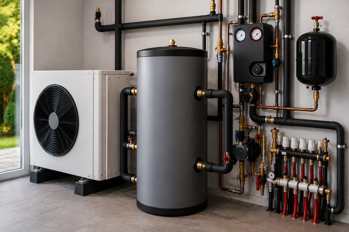
A volumiser is an insulated vessel installed within the heating circuit to increase the total volume of system water.
Unlike a domestic hot water cylinder, it does not store water for household use. Unlike a buffer vessel, it is not intended to separate the primary and secondary hydraulic circuits.
Its purpose is to increase the amount of circulating water available to the heat pump.
This additional water helps the heat pump maintain stable operating conditions and can reduce unnecessary compressor cycling where the existing heating system does not provide sufficient water volume.
Because the water continues to circulate through the volumiser as part of the main heating circuit, installation is relatively straightforward compared with systems requiring hydraulic separation.
Why Manufacturers Specify Volumisers
Every heat pump manufacturer designs its equipment to operate within specific hydraulic conditions.
One of those conditions is the minimum amount of water circulating through the system.
If insufficient water is available, the heat pump may respond too quickly to changing temperatures. Rather than operating steadily, it may repeatedly switch on and off as it reaches its target flow temperature within a short period.
This operating pattern reduces efficiency and increases mechanical wear on the compressor.
Where the existing heating system does not contain sufficient water, manufacturers may recommend installing a volumiser rather than a buffer vessel.
A volumiser increases water content while maintaining a simple heating circuit, making it suitable for installations that do not require hydraulic separation.
Minimum System Water Volume
Every heating system naturally contains water within its pipework, radiators, underfloor heating circuits and heat exchangers.
The total volume depends on factors including:
- Heat pump output
- Pipework diameter
- Pipework length
- Radiator size
- Underfloor heating circuits
- Hot water cylinder coil
- Ancillary components
Smaller systems or highly insulated properties may contain less water than the heat pump manufacturer recommends.
Where this occurs, a volumiser can increase the system volume without changing the hydraulic arrangement.
The following table illustrates typical minimum system water volumes used by various manufacturers. These values are examples only, and installers should always refer to the technical documentation for the specific heat pump being installed.
| Heat Pump Output | Example Minimum System Volume |
|---|---|
| 5 to 7kW | Approximately 50 to 70 litres |
| 8 to 10kW | Approximately 80 to 100 litres |
| 12 to 16kW | Approximately 120 to 150 litres |
| 16kW and Above | Manufacturer specific |
Calculating the total system water content during the design stage allows heat pump installers to determine whether additional volume is required before installation begins.
Water Volume
Unlike conventional boilers, heat pumps are designed to transfer heat gradually into the heating system.
The water circulating through the system acts as a thermal store, absorbing energy produced by the heat pump before transferring it into the property through radiators or underfloor heating.
Where sufficient water volume is available, temperature changes occur more gradually.
This allows the compressor to operate for longer periods while maintaining stable flow temperatures.
Where water volume is too low, temperatures rise rapidly, causing the heat pump to reach its target temperature prematurely.
This can lead to repeated compressor starts and stops that reduce efficiency.
Increasing system water volume allows the heat pump to operate in a more controlled and stable manner.
Compressor Cycling
Compressor cycling is one of the primary reasons volumisers are specified.
Each time a compressor starts, electrical demand increases and mechanical components experience additional stress.
Repeated cycling may result in:
- Higher electricity consumption
- Reduced seasonal efficiency
- Increased compressor wear
- Less stable room temperatures
- Reduced operating efficiency
A volumiser increases the thermal mass within the heating circuit, allowing the compressor to remain in operation for longer before reaching its target temperature.
This creates smoother system operation and supports the low-temperature heating principles on which heat pumps rely.
Volumiser Operation
A volumiser is connected directly into the heating circuit using two pipe connections.
Unlike a buffer vessel, it does not create separate hydraulic circuits.
Water entering the volumiser continues through the heating system without changing direction or passing between independent circulation loops.
This means the volumiser becomes part of the heating circuit itself.
Its operation is passive.
There are no moving components, controls or electrical connections.
Once installed, it continuously increases the available system water volume throughout normal heating operation.
Volumiser Versus Buffer Vessel
Although volumisers and buffer vessels both increase the amount of water within a heating system, they are designed for different purposes.
A volumiser is intended solely to increase system water content.
A buffer vessel can also increase water volume but may additionally provide hydraulic separation between primary and secondary circuits.
Selecting the correct component depends entirely upon the hydraulic design of the installation.
| Volumiser | Buffer Vessel |
|---|---|
| Increases system water volume | Increases system water volume |
| No hydraulic separation | Can provide hydraulic separation |
| Installed directly within the heating circuit | May separate primary and secondary circuits |
| Simple two port arrangement | Usually two or four port arrangement |
| Suitable where only additional water volume is required | Suitable where hydraulic separation is also required |
Understanding this distinction allows installers to avoid specifying larger or more complex components where a simpler solution would achieve the required result.
Volumiser Sizing
Selecting an appropriate volumiser requires more than matching it to the heat pump output.
Installers should consider:
- Existing system water volume
- Heat pump capacity
- Manufacturer requirements
- Pipework volume
- Radiator water content
- Underfloor heating water content
- Future system expansion
The objective is to increase the total water volume sufficiently to satisfy the manufacturer’s minimum requirement without introducing unnecessary standing heat losses or increasing installation costs.
The following table provides general guidance only.
| Heat Pump Output | Typical Volumiser Size |
|---|---|
| 5 to 8kW | 20 to 30 litres |
| 8 to 12kW | 30 to 50 litres |
| 12 to 16kW | 50 to 80 litres |
| Above 16kW | Calculated to suit the installation |
These figures should always be confirmed against the manufacturer’s installation instructions and the calculated water content of the complete heating system.
Installation Position
Volumisers are normally installed in series within the heating circuit so that all circulating water passes through the vessel.
Depending on the manufacturer’s guidance and the overall system design, they may be installed on either the flow or return pipework.
When selecting the installation position, installers should also consider:
- Ease of maintenance
- Air removal
- Drainage points
- Pipe insulation
- Sensor locations
- Available plant room space
Correct positioning helps maintain efficient circulation while simplifying servicing and future maintenance.
System Design Considerations
The decision to install a volumiser should be based on the hydraulic requirements of the heating system rather than adopting the same approach for every installation.
During the design stage, installers should assess the calculated system water volume alongside the manufacturer’s recommendations.
If sufficient water volume already exists within the pipework, radiators and underfloor heating circuits, an additional volumiser may not provide any operational benefit.
Where additional volume is required, however, a volumiser offers a straightforward method of achieving the required water content while maintaining a simple hydraulic layout.
Volumisers With Radiator Systems
Radiator systems are often suitable for volumisers where the only objective is to increase system water volume.
This is particularly relevant during retrofit heat pump installations where existing radiators have been replaced or upgraded to operate at lower flow temperatures. Still, the total water content of the heating system remains below the manufacturer’s minimum requirement.
A volumiser increases the available water volume without altering the hydraulic layout of the system.
Where the heating circuit remains relatively simple, with a single circulation pump and no requirement for hydraulic separation, a volumiser may provide an effective solution.
Installers should still verify that radiator sizing, flow rates and balancing have been completed correctly, as increasing water volume alone will not resolve design or commissioning issues.
Volumisers With Underfloor Heating
Underfloor heating systems naturally contain a greater volume of water than most radiator installations because of the length of pipework installed beneath the floor.
In many cases, this means the heating system already satisfies the manufacturer’s minimum water volume requirements.
However, this should never be assumed.
Properties with smaller underfloor heating zones or hybrid systems may still require additional system volume.
Before specifying a volumiser, installers should calculate the total water content of the heating system and compare this with the manufacturer’s guidance.
If sufficient volume already exists, adding a volumiser may provide little practical benefit.
Mixed Emitter Systems
Properties incorporating both radiators and underfloor heating require additional consideration.
The heating system may include:
- Radiators upstairs
- Underfloor heating downstairs
- Multiple heating zones
- Independent circulation pumps
- Motorised valves
Where hydraulic separation is unnecessary, but additional water volume is required, a volumiser may still be appropriate.
If independent primary and secondary circuits are required, however, a buffer vessel may provide the more suitable solution.
The decision should always be based on the hydraulic design rather than the type of heat emitters alone.
Weather Compensation and Volumisers
Weather compensation continuously adjusts the flow temperature according to outdoor conditions.
A correctly sized volumiser should have little effect on the operation of weather compensation because it remains part of the main heating circuit.
Unlike an oversized buffer vessel, which may slow system response under certain conditions, a volumiser increases thermal mass without introducing additional hydraulic complexity.
This allows weather compensation to continue adjusting flow temperatures efficiently while benefiting from improved operating stability.
Correct commissioning remains essential to ensure both components operate together as intended.
Advantages Of Volumisers
Where additional water volume is required, volumisers offer several benefits.
These include:
- Increased system water content
- Reduced compressor cycling
- Improved operating stability
- Simpler installation than hydraulic separation
- Lower installation cost than a buffer vessel
- Reduced pipework requirements
- Compatibility with straightforward heating circuits
These advantages make volumisers particularly suitable for simpler heating systems where hydraulic separation is not required.
Design Limitations
Although volumisers offer several advantages, they should not be viewed as the solution for every installation.
A volumiser cannot:
- Provide hydraulic separation
- Resolve balancing issues
- Correct undersized radiators
- Increase heat pump capacity
- Compensate for inaccurate heat loss calculations
- Resolve poor commissioning
If these issues exist, installing a volumiser alone will not improve system performance.
Understanding the purpose of the component is therefore essential during system design.
Installation Errors
Incorrect installation can reduce the effectiveness of a volumiser.
Examples include:
- Incorrect pipe orientation
- Poor insulation
- Installing an oversized vessel
- Installing an undersized vessel
- Incorrect sensor positioning
- Air trapped within the vessel
- Poor system flushing before installation
Attention to detail during installation helps ensure the volumiser performs as intended throughout the heating system.
Fault Finding Volumiser Problems
A volumiser contains no moving parts and requires very little maintenance.
However, installers should still inspect it during fault finding if heating performance issues are reported.
Areas to check include:
- Air accumulation
- Water circulation
- Pipe insulation
- Isolation valve positions
- Temperature distribution
- System pressure
The volumiser itself is rarely the cause of a heating fault.
Instead, it should be assessed as part of the wider hydraulic system.
| Reported Issue | Possible Cause |
|---|---|
| Frequent compressor cycling | Insufficient system water volume or incorrect vessel sizing |
| Poor heating performance | Flow rate, balancing or commissioning issue |
| High electricity consumption | Incorrect flow temperatures or control settings |
| Air noises within the system | Air trapped during filling or maintenance |
| Uneven room temperatures | Hydraulic balancing or emitter performance |
A systematic approach allows installers to identify the true source of a fault rather than replacing components unnecessarily.
Installation Example
Consider a newly built three-bedroom detached property fitted with an 8kW air source heat pump.
The heating system consists of oversized low-temperature radiators connected to a single heating circuit.
Following completion of the design calculations, the installer determines that the total system water content is below the manufacturer’s minimum requirement.
The hydraulic design does not require separate primary and secondary circuits, and only one circulation pump is installed.
Rather than fitting a buffer vessel, the installer specifies a correctly sized volumiser to increase the total water content while maintaining the existing hydraulic arrangement.
Following commissioning, the heat pump operates with longer compressor run times, improved operating stability and reduced cycling, while retaining the simplicity of a single heating circuit.
Choosing Between a Volumiser and a Buffer Vessel
Selecting the correct component begins with understanding the purpose of each device.
The following questions provide a useful starting point during system design.
| Design Question | Likely Solution |
|---|---|
| Is additional water volume required? | Volumiser or buffer vessel |
| Is hydraulic separation required? | Buffer vessel |
| Does the system use multiple circulation pumps? | Usually a buffer vessel |
| Is the heating circuit straightforward with a single pump? | Volumiser may be suitable |
| Does the manufacturer specify hydraulic separation? | Follow manufacturer guidance |
Each installation should be assessed individually. The objective is to provide the hydraulic arrangement that best supports the heat pump rather than selecting components based on routine practice.
Heat Pump Training in Staffordshire
Understanding the role of volumisers forms part of a wider knowledge of renewable heating system design.
At Staffordshire Training Services, our Air Source Heat Pump Systems (Level 3), Ground Source Heat Pump Systems (Level 3) and Air and Ground Source Heat Pump Systems Combined Course (Level 3) provide engineers with the technical understanding required to design, install and commission efficient heat pump systems.
Renewable energy systems training covers heat loss calculations, low temperature heating principles, system water volume, hydraulic design, emitter selection, weather compensation, commissioning procedures and fault finding. By understanding the purpose of components such as volumisers and buffer vessels, engineers can make informed design decisions that support efficient and reliable heat pump operation.
As renewable heating technologies continue to develop, a strong understanding of hydraulic principles enables installers to produce heating systems that perform in accordance with manufacturer requirements while delivering efficient and dependable comfort for their customers.
Related Articles
- Heat Pump Fault Finding For Renewable Installers
- Buffer Vessels in Heat Pump Systems
- Heat Pump Commissioning Procedures For Renewable Installers
- Weather Compensation and Heat Pump Efficiency
- Low Temperature Heating Systems For Renewable Installers
Prefer an AI Summary?